


Sample Configurations
G-5
3920-A2-GN31-30
November 1996
3910 A
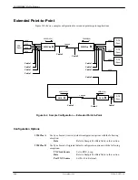
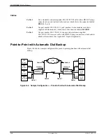
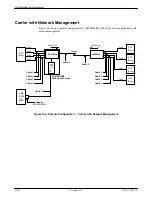
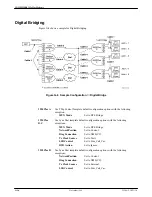
Use Sync Leased (Answer) default configuration options with the following
exceptions:
TX Clock Source
Set to External.
LeasedLine Rate
Set to 4800(V32b).
Autorate (Leased Line) Set to Disable.
3910 B
Use Sync Leased (Originate) default configuration options with the following
exceptions:
TX Clock Source
Set to RXC_Loop.
LeasedLine Rate
Set to 4800(V32b).
Autorate (Leased Line) Set to Disable.
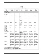
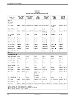
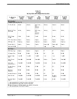
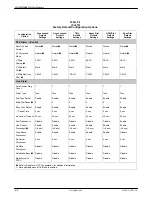
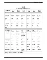
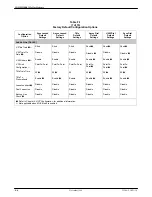
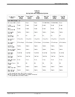
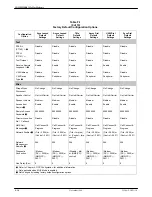
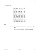
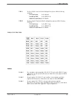
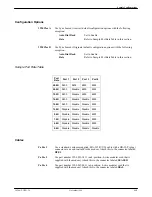
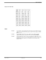
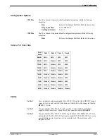
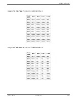
Sample Port Rate Table
Port
Rate
Port 1
Port 2
Port 3
Port 4
ÁÁÁ
ÁÁÁ
28.8K
ÁÁÁÁ
ÁÁÁÁ
9600
ÁÁÁÁ
ÁÁÁÁ
9600
ÁÁÁ
ÁÁÁ
4800
ÁÁÁÁ
ÁÁÁÁ
4800
ÁÁÁ
ÁÁÁ
24.0K
ÁÁÁÁ
ÁÁÁÁ
9600
ÁÁÁÁ
ÁÁÁÁ
Disable
ÁÁÁ
ÁÁÁ
4800
ÁÁÁÁ
ÁÁÁÁ
4800
ÁÁÁ
Á
ÁÁ
19.2K
ÁÁÁÁ
Á
ÁÁ
Á
9600
ÁÁÁÁ
Á
ÁÁ
Á
Disable
ÁÁÁ
Á
Á
Á
4800
ÁÁÁÁ
Á
ÁÁ
Á
4800
ÁÁÁ
Á
ÁÁ
ÁÁÁ
16.8K
ÁÁÁÁ
Á
ÁÁ
Á
ÁÁÁÁ
9600
ÁÁÁÁ
Á
ÁÁ
Á
ÁÁÁÁ
Disable
ÁÁÁ
Á
Á
Á
ÁÁÁ
Disable
ÁÁÁÁ
Á
ÁÁ
Á
ÁÁÁÁ
4800
ÁÁÁ
ÁÁÁ
14.4K
ÁÁÁÁ
ÁÁÁÁ
9600
ÁÁÁÁ
ÁÁÁÁ
Disable
ÁÁÁ
ÁÁÁ
Disable
ÁÁÁÁ
ÁÁÁÁ
4800
ÁÁÁ
ÁÁÁ
12.0K
ÁÁÁÁ
ÁÁÁÁ
Disable
ÁÁÁÁ
ÁÁÁÁ
Disable
ÁÁÁ
ÁÁÁ
Disable
ÁÁÁÁ
ÁÁÁÁ
4800
ÁÁÁ
Á
ÁÁ
ÁÁÁ
9.6K
ÁÁÁÁ
Á
ÁÁ
Á
ÁÁÁÁ
Disable
ÁÁÁÁ
Á
ÁÁ
Á
ÁÁÁÁ
Disable
ÁÁÁ
Á
Á
Á
ÁÁÁ
Disable
ÁÁÁÁ
Á
ÁÁ
Á
ÁÁÁÁ
4800
ÁÁÁ
Á
ÁÁ
ÁÁÁ
7.2K
ÁÁÁÁ
Á
ÁÁ
Á
ÁÁÁÁ
Disable
ÁÁÁÁ
Á
ÁÁ
Á
ÁÁÁÁ
Disable
ÁÁÁ
Á
Á
Á
ÁÁÁ
Disable
ÁÁÁÁ
Á
ÁÁ
Á
ÁÁÁÁ
4800
ÁÁÁ
ÁÁÁ
4.8K
ÁÁÁÁ
ÁÁÁÁ
Disable
ÁÁÁÁ
ÁÁÁÁ
Disable
ÁÁÁ
ÁÁÁ
Disable
ÁÁÁÁ
ÁÁÁÁ
4800
ÁÁÁ
ÁÁÁ
2.4K
ÁÁÁÁ
ÁÁÁÁ
Disable
ÁÁÁÁ
ÁÁÁÁ
Disable
ÁÁÁ
ÁÁÁ
Disable
ÁÁÁÁ
ÁÁÁÁ
Disable
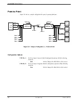
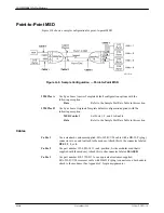
Cables
Cable 1
Use a standard, customer-supplied, EIA-232-D/V.24 cable with a DB-25-P (plug)
connector at one end to attach to the modem. Attach this to the connector labeled
DTE1, 2, 3, or 4.
Cable 2
Use part number 125-0053-1431 (an 8-position, 8-wire modular cord that is
supplied with the modem). Attach this to the connector labeled LEASED.
Cable 3
Use part number 818-2759-0111 or an equivalent customer-supplied,
EIA-232-D/V.24 crossover cable with DB-25-P (plug) connectors on both ends to
attach to the modems. (See Appendix C for pin assignments.)


