Paradyne COMSPHERE 3910 Installation Instructions Manual Download Page 9

9

DTE Connection

Use the following procedures to connect the EIA-232-D cable from the modem to the DTE:

1. Make sure the modem’s rear panel power switch is OFF.

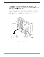
2. Connect the DB-25-P (plug) connector on the cable to the DB-25-S (socket) connector labeled DTE

(Figure 1) on the modem’s rear panel. Use a small screwdriver to secure the cable to the modem.

3. Connect the DB-25-P connector on the cable to the DB-25-S connector on the DTE. Use a small

screwdriver to secure the cable to the DTE.

Model 3910 4-Wire/2-Wire Leased-Line Connection

Use the following procedures to connect a Model 3910 to the leased-line network interface:

1. Insert the 8-position, 8-conductor modular plug into the jack labeled LEASED (Figure 1).

2. Insert the other end of the modular cord into the leased-line network interface.

3. If the Model 3910 has a dial backup line, follow the steps listed in the Model 3910 Dial-Line Connection

section.

Dial Network Connection

The telephone company provides the line termination jacks for the permissive service you request. Advance
coordination with the telephone company is suggested when connecting the modem to telephone dial lines
(PSTN).

In the Permissive mode, the modem’s transmit output level is fixed at –9 dBm. The telephone company assumes
that the line loss is 3 dB and no compensation is provided for additional losses. A Permissive mode telephone line
is usually terminated with a USOC RJ11C jack.

Model 3910 Dial-Line Connection

For the Model 3910, use the following procedures to connect the modem to the dial network interface:

1. Insert the 6-position, 4-conductor modular plug into the jack labeled DIAL (Figure 1).

2. Insert the other end of the modular cord into the dial network interface.

Network Management System Connection

For the Model 3910, use the following procedures to connect the modem to the network management system
interface:

1. Insert the sub-miniature, 4-conductor modular plug of the 3600 Hubbing Device into the jack labeled

NMS (Figure 1). Refer to Document Number, 3610-A2-GZ45, 3600 Hubbing Device Feature
Number 3600-F3-300, Installation Instructions
, for a description of the 3600 Hubbing Device. 
Installation for the 3910 is the same as for the 3610 DSU.

2. Connect the 3600 Hubbing Device to the network management channel.

Summary of Contents for COMSPHERE 3910

Page 1: ...o be used in conjunction with the COMSPHERE 3900 Series Modems Models 3910 and 3911 Point to Point Multipoint Installation and Operation Manual Document No 3910 A2 GN32 Warranty Sales and Service Info...

Page 2: ...General purpose cables are provided with this product Special cables which may be required by the regulatory inspection authority for the installation site are the responsibility of the customer 7 Whe...

Page 3: ...3 Notices...

Page 4: ...ided to the telephone company 2 An FCC compliant telephone cord and modular plug is provided with this equipment This equipment is designed to be connected to the telephone network or premises wiring...

Page 5: ...rporation commission for information Canada NOTICE TO THE USERS OF THE CANADIAN PUBLIC SWITCHED TELEPHONE NETWORK The Canadian Department of Communications label identifies certified equipment This ce...

Page 6: ...ation on a loop may consist of any combination of devices subject only to the requirement that the total of the Load Numbers of all devices does not exceed 100 If your equipment is in need of repair r...

Page 7: ...le NIM for modems installed in Slots 1 8 and one NIM for modems installed in Slots 9 16 required for dial line applications For installation of the COMSPHERE 3000 Series Carrier into a cabinet refer t...

Page 8: ...or the DTE interface Connecting Model 3910 Modems with Supplied Cables Figure 1 shows how Model 3910 modems are connected to certain TELCO jack types using the appropriate cables 8 POSITION 8 CONDUCTO...

Page 9: ...st Advance coordination with the telephone company is suggested when connecting the modem to telephone dial lines PSTN In the Permissive mode the modem s transmit output level is fixed at 9 dBm The te...

Page 10: ...f the LCD Although a failure has occurred the modem will attempt to operate This allows you to activate a more thorough self test using the Test branch For a better understanding of the Test branch re...

Page 11: ...ng configuration options to the Active Saved configuration area automatically saves them to the Active Operating configuration area The LCD displays Command Complete 7 The modem is now configured with...

Page 12: ...o use AT commands after saving a factory configuration Other selections remove AT command control The only way to return to AT command control is through the DCP as described earlier in Using the DCP...

Page 13: ...signed for installation in a COMSPHERE 3000 Series Carrier which supplies both the operating power and the leased and or dial network connections For correct power DTE dial line leased line and networ...

Page 14: ...up self test in which all faceplate LEDs light Return to the rear of the carrier and tighten the rear connector plate Figure 2 Installing a Model 3911 Modem If the modem is to communicate with an ins...

Page 15: ...t 6 Once you have determined that the modem is installed properly and completed its power up self test rotate the circuit pack lock until it covers the faceplate latch Figure 3 and tighten the retenti...

Page 16: ...y to power down the carrier to remove and replace a Model 3911 modem Perform the following steps 1 Rotate the circuit pack lock until the release tab is exposed 2 Press down on the release tab and pul...

Page 17: ...x Frame Size RdcdAsyncBufSiz Test DTE RL CT140 DTE LL CT141 Test Timeout Rcv Remote Loop V54 Address V54 Device Type Misc StrapsWhenDisc Speaker Control Speaker Volume Access frm Remt RemAccssPasswrd...

Reviews: