


14
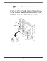
2. At the front of the carrier, hold the modem vertically, with the latch on its faceplate in the open position,
and insert it into the top and bottom card guides of one of the slots numbered 1–16 (Figure 2).
Slide the modem into the slot, aligning the modem with the rear connector plate, until the backplane
connector and DTE connector seat firmly into the back of the carrier. The faceplate latch automatically
closes as you push the modem into the carrier. To lock the modem into the carrier, press the faceplate latch
until a “click” is heard.
3. If the carrier is ON, the Power LED on the faceplate of the 3911 lights. After several seconds the modem
completes its power-up self-test, in which all faceplate LEDs light.
Return to the rear of the carrier and tighten the rear connector plate.
Figure 2. Installing a Model 3911 Modem
If the modem is to communicate with an installed SDCP, install the modem as described above and perform the
following steps:
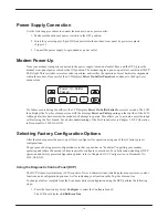
1. Press the
Select
key on the SDCP. The cursor appears in the carrier selection entry.
2. Press the F1 (
) or F2 (
) key until the carrier number you want appears on the LCD.
The carrier number selection has a range of 1 to 8 since a single SDCP can control a configuration of up
to eight carriers. (This is only possible if the SDU is installed.)
3. Press the
key to position the cursor on the slot selection entry.
4. Press the F1 (
) or F2 (
) key until the slot number you want (1–16) appears on the LCD. Ignore the
AB designator that appears on the LCD since it is not applicable to the 391x Series modems.
Summary of Contents for COMSPHERE 3910
Page 3: ...3 Notices...