


IPR512-EQ03 09/2009
Page 6
PARADOX.COM
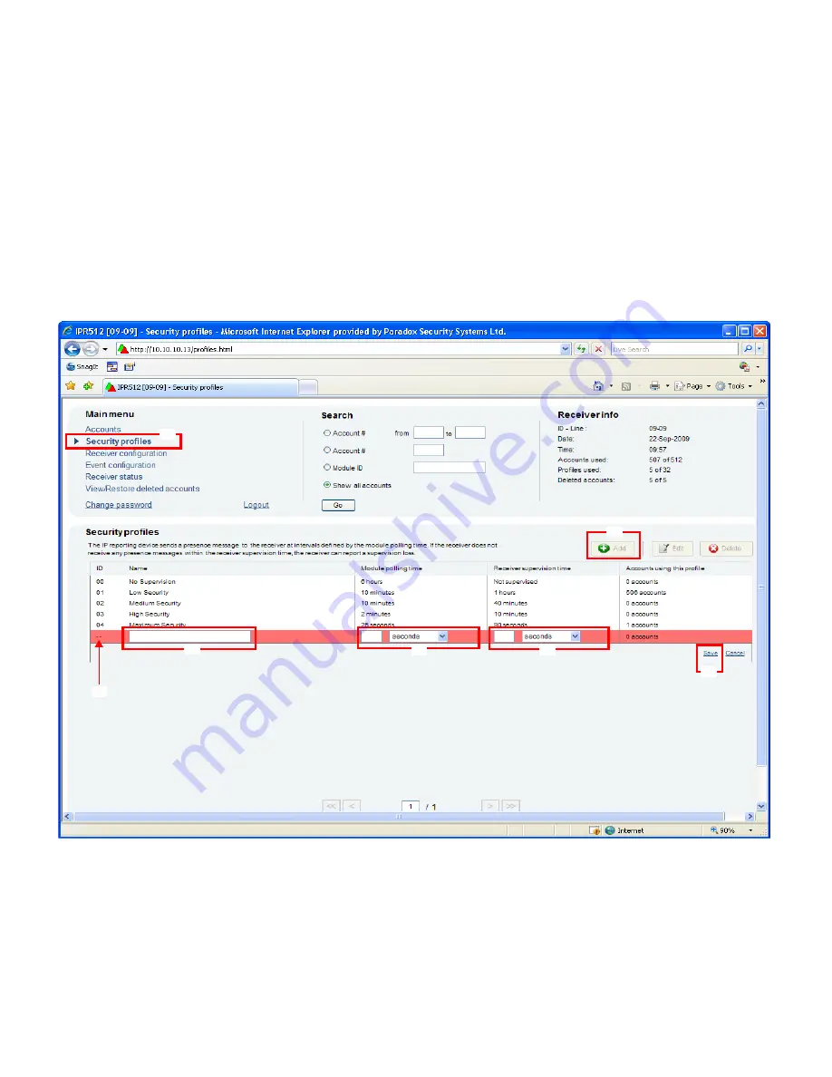
Step 12: Set Security Profile
The receiver supervises the presence of up to 512 assigned Paradox reporting modules. Up to 32 security profiles can be created
per receiver with a programmable polling time (seconds, minutes, or hours). These profiles are then assigned to each module
during registration. The module will send a presence message (~100 bytes) at intervals defined by the Module Polling Time. If the
receiver does not receive at least one presence message from the module within the Receiver Supervision Time, the receiver can
report a communication loss to the Automation Software, refer to Step 11: Event Configuration on page 5.
1) From the Main Menu, click
Security Profiles
.
2)
Click the
Add
button.
3)
Type a name for the new security profile.
4)
In the Module Polling Time column type a 2-digit value and select a base time from the drop down list. Represents interval at
which the Paradox reporting module will send a presence message.
5)
In the Receiver Supervision Time column type a 2-digit value and select base time from the drop down list. This value must
be higher than the Module Polling Time. Represents the time the receiver will wait before reporting a communication loss.
6)
Click
Save
.
7)
The ID column represents the 2-digit value used by the installer when registering a Paradox reporting module to the receiver.
This number is automatically generated by the system.
NOTE: For the Receiver Supervision Time (item #5), Paradox recommends a minimum value of 1 minute. Also, the Module Polling Time (item
#4) must be at least than half the Receiver Supervision Time (e.g., RST: 1 minute - MPT: 30 sec.)
1
2
3
4
5
6
7


