


IPR512-EQ03 09/2009
Page 2
PARADOX.COM
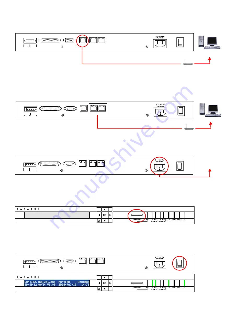
Step 3: Connect LAN
(Web Page Interface)
Connect the receiver to a router on a network. A computer on the network will be used to access the receiver’s internal web page
interface in order to configure the receiver. Connect a CAT5 network cable between the receiver’s LAN connector and the router
of the network.
Step 4: Connect WAN Port(s)
(Internet Service Provider)
Connect the receiver to a router on a network with access to the Internet. System events are sent through the internet to the WAN
port of the receiver defined by the IP address and port set in the control panel. Connect a CAT5 network cable between the
receiver’s WAN1 connector and the router of a network with internet access. Connect WAN2 to another router and network to
provide redundant reporting through a different Internet Service Provider (ISP).
Note: The router must be installed in the same room as the IPR512 GPRS/IP Monitoring Receiver.
Step 5: Connect Power
Connect the AC power cable (included) between the plug at the back of the receiver and an Uninterruptible Power Supply (UPS).
Note: To comply with applicable UL and CSA requirements, a Belkin Surge Protector (part number F9H120-CW) must be used between the
IPR512’s AC power cable and the electrical outlet or UPS source.
Step 6: Insert Memory Card
(Data Backup)
Insert memory card (included) into the Memory Card slot. The IPR512 supports any external SD, SD/HC, or MMC memory card.
The receiver backs up data automatically (receiver configuration and account information) 10 minutes after a change has been
made in the database. Manual backups can be performed from the receiver LCD menu, refer to the IPR512 GPRS/IP Monitoring
Receiver Operations Manual for details.
Step 7: Power Up
Turn on the receiver by pressing the on/off switch. The receiver will go through an initialization process. When complete, the LCD
will display system information and the WAN, LAN and AC lights will be ON as shown below.
Note: If the TROUBLE light is ON, please refer to Trouble and LED Display on page 7. However, as long as the AC and LAN lights are on, you
can proceed to step 8.
COM
1
(PC)
COM
2
(SERIAL OUT)
LAN
WAN
1
WAN
2
INPUT
TRIGGER
C
1 COM NO
OUTPUT
RELAY
I
O
P A R A D O X . C O M
Network
PC
Router
COM
1
(PC)
COM
2
(SERIAL OUT)
LAN
WAN
1
WAN
2
INPUT
TRIGGER
C
1 COM NO
OUTPUT
RELAY
I
O
P A R A D O X . C O M
WAN
Router
COM
1
(PC)
COM
2
(SERIAL OUT)
LAN
WAN
1
WAN
2
INPUT
TRIGGER
C
1 COM NO
OUTPUT
RELAY
I
O
P A R A D O X . C O M
UPS
Uninterruptible
Power Supply
IP Monitoring Receiver
IPR512
COM
1
(PC)
COM
2
(SERIAL OUT)
LAN
WAN
1
WAN
2
INPUT
TRIGGER
C
1 COM NO
OUTPUT
RELAY
I
O
P A R A D O X . C O M
IP Monitoring Receiver
IPR512


