IPR512-EQ03 10/2009
IPR512 V2.0
PARADOX.COM
IPR512: GPRS/IP Monitoring Receiver V2.0
Quick Start
The following instructions explain the basic connections and programming required to get your Paradox IPR512 GPRS/IP
Monitoring Receiver up and running. They also guide the installer on how to register the Paradox reporting module (IP100 Internet
Module or PCS Module) to the receiver. For more detailed information, please refer to the IPR512 GPRS/IP Monitoring Receiver
Operations Manual.
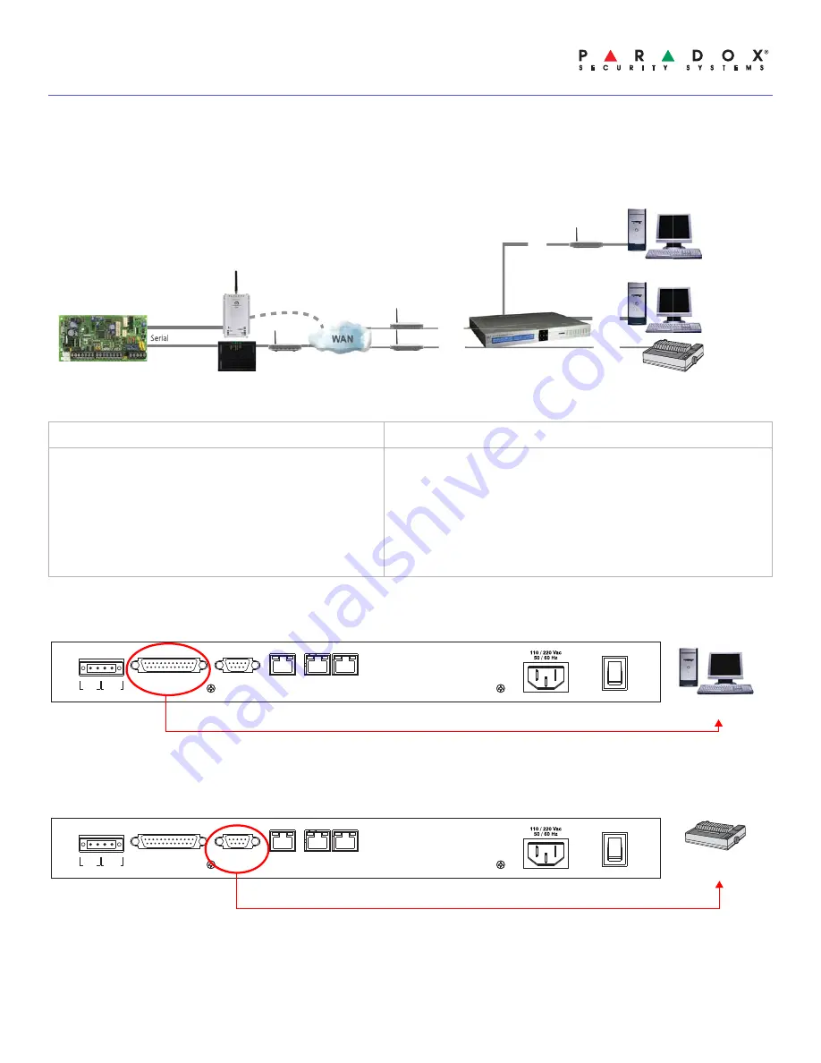
Figure 1: System Overview
Step 1: Connect COM1
(Automation Software)
Connect the receiver to a PC running the automation software. Connect the provided 3m (10ft) DB25 to DB9 cable between the
receiver’s COM1 connector and a COM port on the PC, or on the PC’s serial hub.
Step 2: Connect COM2
(Optional: Serial printer/PC)
This step is optional. Connect the receiver to a serial printer or to a PC running
RS232 serial communication software
. The
receiver sends reported events in plain text format through COM2 (RS-232), which can be printed or viewed. Connect a serial
cable between the receiver’s COM2 (DB9) connector and a COM port on the serial printer or PC (gender changer is included).
Out of the Box (included):
Additional Items Required (not included)
•
Paradox IPR512 GPRS/IP Monitoring Receiver
•
2GB memory card
•
1.8m (6ft) power cable
•
3m (10ft) DB25 to DB9 serial cable for COM1
•
DB9 gender changer
•
Rack-mount kit (brackets and screws)
•
Desktop installation kit (rubber feet)
•
Removable connector for Input/Output Relay
•
CAT5 network cable for LAN and WAN1/WAN2
•
Optional: DB9 or DB25 serial cable (RS-232) for COM2
•
Router and computer on a network to access internal web page
interface (LAN)
•
Router on a network with internet access (WAN1) to receive
control panel report codes
Serial
LAN
WAN1
WAN2
COM1
COM2
Paradox Control
Panel
Paradox IPR512
GPRS/IP Monitoring Receiver
(IPR512)
Paradox Internet
Module (IP100)
Paradox Communicator Module
(PCS Series)
Router
Routers
Web Page
Interface
Automation
Software
Serial printer/
PC
COM
1
(PC)
COM
2
(SERIAL OUT)
LAN
WAN
1
WAN
2
INPUT
TRIGGER
C
1 COM NO
OUTPUT
RELAY
I
O
P A R A D O X . C O M
Automation
Software
COM
1
(PC)
COM
2
(SERIAL OUT)
LAN
WAN
1
WAN
2
INPUT
TRIGGER
C
1 COM NO
OUTPUT
RELAY
I
O
P A R A D O X . C O M
Serial printer/
PC


