


IPR512: IP Monitoring Receiver
2 of 8
Quick Start
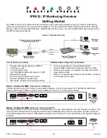
Step 3: Connect LAN
(Web Page Interface)
Connect the receiver to a router on a network. A computer on the network will be used to access the receiver’s internal web
page interface in order to configure the receiver. Connect a CAT5 network cable between the receiver’s LAN connector and
the router of the network.
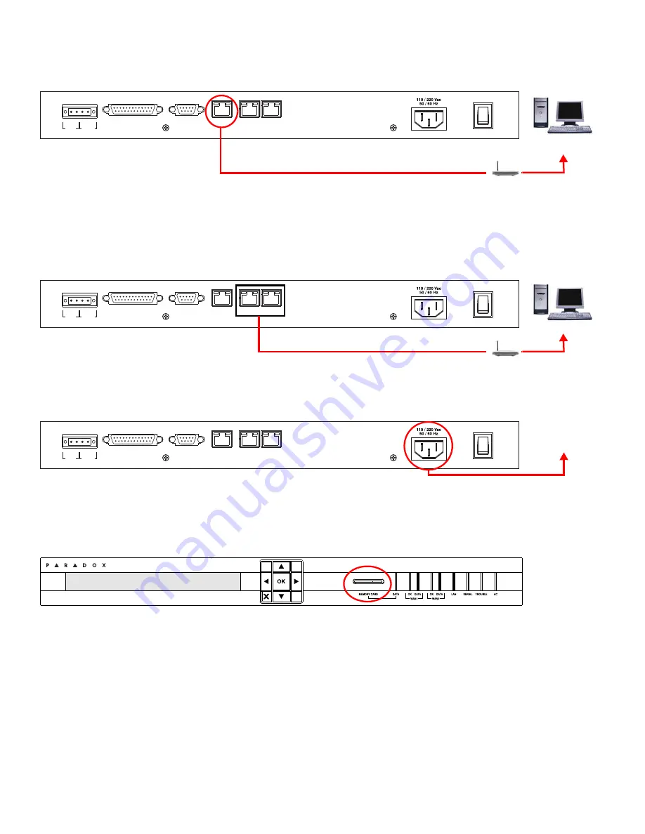
Step 4: Connect WAN1
(Internet Service Provider)
Connect the receiver to a router on a network with access to the internet. System events are sent through the internet to the
WAN port of the receiver defined by the IP address and port set in the control panel. Connect a CAT5 network cable
between the receiver’s WAN1 connector and the router of a network with internet access. Connect WAN2 to another router
and network to provide redundant reporting through a different Internet Service Provider (ISP).
Note: WAN2 is not
available on the present version. Check the Web for updates.
Step 5: Connect Power
Connect the AC power cable (included) between the plug at the back of the receiver and an Uninterruptible Power Supply
(UPS).
Step 6: Insert Memory Card
(Data Backup)
Insert memory card (minimum 1GB recommended) into the Memory Card slot. The IPR512 supports any external SD, SD/
HC, or MMC memory card. The receiver backs up data (receiver configuration and account information) at programmable
intervals (default: every 2 hours). Manual backups can be performed from the receiver LCD menu (see IPR512 Operating
Manual for details).
COM
1
(PC)
COM
2
(SERIAL OUT)
LAN
WAN
1
WAN
2
INPUT
TRIGGER
C
1 COM NO
OUTPUT
RELAY
I
O
P A R A D O X . C O M
Network
PC
Router
COM
1
(PC)
COM
2
(SERIAL OUT)
LAN
WAN
1
WAN
2
INPUT
TRIGGER
C
1 COM NO
OUTPUT
RELAY
I
O
P A R A D O X . C O M
WAN
Router
COM
1
(PC)
COM
2
(SERIAL OUT)
LAN
WAN
1
WAN
2
INPUT
TRIGGER
C
1 COM NO
OUTPUT
RELAY
I
O
P A R A D O X . C O M
UPS
Uninterruptible
Power Supply
IP Monitoring Receiver
IPR512


