background image

IC Block Diagrams

-7-

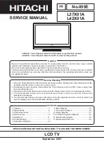
IC001 < Audio AMP. > LA4266-E

1

2

3

PRE 
GND

4

6

7

8

9

NC

10

AMP

5

POWER 
GND

NC

FILTER

NC

VCC

INPUT

OUT
PUT

NFL

30K

300

Thermal

Protection

-

+

AMP

Pump

Up

1

INVER

TING 

INPUT

2

Vcc

3

PUMP UP

OUT

4

GND

5

Ve

r.

 OUTPUT

6

OUTPUT 

ST

A

GE Vcc

7

NON INV

.

INPUT

IC501 < Vertical Output > LA78040N-E, TDA9302H

Summary of Contents for TVP-2015AD

Page 1: ...er to the specifi cation table Specifications Power Source AC220V 50Hz 60Hz Receiving System PAL M M N N NTSC M M Channel Coverage Antenna mode VHF CH02 CH13 UHF CH14 CH69 CATV mode VHF band CH01 CH13...

Page 2: ...eiver is the picture tube The picture tube is specially con structed to limit X RADIATION emissions For continued X RADIATION protection the replacement tube must be the same type as the original incl...

Page 3: ...001 K1002A REAR AV IN FRONT AV IN VIDEO VIDEO AUDIO AUDIO 19 20 21 R G B 7 AC POWER CIRCUIT CONVERTER TRANS 130V MAIN HIGH 20V AUDIO 12V MAIN LOW 24V VERT 9V IC202 REG IC 5V 2 REG IC IC681 5VRC 27 23...

Page 4: ...GH IC001 AUDIO AMP RESET IN RESET LOW KEY SWITCH KEY SWITCH IN RC PRE AMP RC SIGNAL IN RELAY ON OFF OUT FOR DEGAUSSING ON HIGH POWER ON OFF OUT LED RED POWER CIRCUIT SDA SCL A101 TUNER IC201 IF VIDEO...

Page 5: ...MP V C VCC 5V 46 47 48 49 50 A2C PLL 51 52 53 54 Audio Output FM Output Selected Audio Output PIF AGC RF AGC Output PIF Input1 PIF Input 2 IF Ground IF Vcc FM Filter AFT Output Bus Data Bus Clock ABL...

Page 6: ...it Amp 54 10p SIF In Sound BPF VCO Coil VCO COIL1 VCO COIL2 48 49 VIF VCO Chroma Counter B N INV IF Ident OSC C D Amp SIF Sys 2bit pre scaller SIF VCO 500K BPF SIF APC Filter 1K 0 01u 1000p 53 LIM AMP...

Page 7: ...3 PRE GND 4 6 7 8 9 NC 10 AMP 5 POWER GND NC FILTER NC VCC INPUT OUT PUT NFL 30K 300 Thermal Protection AMP Pump Up 1 INVERTING INPUT 2 Vcc 3 PUMP UP OUT 4 GND 5 Ver OUTPUT 6 OUTPUT STAGE Vcc 7 NON IN...

Page 8: ...before attempting the service adjustments See pages 9 10 for detailed information Initial Bus Data Setup Note When IC802 EEPROM is replaced following Service Menu should be set up for proper TV operat...

Page 9: ...evel 26 B YND 0 16 15 Difference value of NTSC B Y DC Level 27 R YND 0 16 15 Difference value of NTSC R Y DC Level 28 G YA 00 00 01 G Y Angle 29 RBGB 08 00 15 R Y B Y Gain Balance 30 RBAG 08 00 15 R Y...

Page 10: ...0 01 H lock V Det RF 72 HLK V 00 00 01 H lock V Det AV 73 VCO SW 00 00 01 C VCO Adjustment SW 74 VCOADJ 03 00 03 C VCO Adjustment 75 GRAY 00 00 01 Gray Mode 76 CROSS 00 00 03 Cross Black White 77 HL S...

Page 11: ...trast to maximum 3 Select Item No 04 V SIZ in the service mode 4 Change value to be optimum vertical size 5 Exit from the service mode 1 Receive a monochrome circular pattern 2 Set the brightness and...

Page 12: ...on to exit from service mode Red Drive 1 Receive a monochrome circular pattern 2 Set the brightness and colour to normal contrast to maximum 3 Enter to the service mode 4 Set each value of Item 16 RBI...

Page 13: ...This function is available for one channel only and the fine tuned channel is memorized into IC802 EEPROM FINE TUNING 1 Enter Service Menu While pressing the MENU button on the television press the 4...

Page 14: ...normal and contrast to maximum 3 Adjust the focus control on the F B T for the best focus on the screen centre FOCUS ADJUSTMENT FOCUS VR Upper side This TV set has a built in power supply protection...

Page 15: ...lours to check this use bias controls Readjust the yoke position if necessary until all screens are pure 7 Adjust each Bias control and screen control to obtain white raster Refer to Gray Scale Adjust...

Page 16: ...L 2 610 260 6317 DEC INLAY F3BA 3 610 260 6676 BUTTON UNITED F3BC 4 610 260 7192 ASSY CABINET FR F3BC 5 610 260 4917 CABINET BACK F3BB 6 645 069 4608 ASSY REMOCON JXMRR 7 610 297 3723 RC BATTERY LID J...

Page 17: ...red when a component replacement is made in any area of a receiver Components indicated by a mark in this parts list and the circuit diagram show components whose value have special significance to pr...

Page 18: ...2 2101 TR 2SC1815 O 405 012 2309 TR 2SC1815 Y 405 157 0505 TR 2SC536NF NPA 405 151 8705 TR 2SC536NG NPA 405 020 7501 TR 2SC945A PA 405 020 7709 TR 2SC945A QA 405 020 7907 TR 2SC945A RA Q693 405 011 84...

Page 19: ...U J 250V C432 403 075 7101 CERAMIC 1000P K 500V C433 403 076 3102 CERAMIC 3900P K 500V C434 403 051 3103 ELECT 47U M 50V C441 403 346 6901 MT POLYPRO 0 22U J 250V C442 403 346 6901 MT POLYPRO 0 22U J...

Page 20: ...R221 401 105 0504 MT GLAZE 1K JA 1 16W R222 401 105 0504 MT GLAZE 1K JA 1 16W R223 401 105 0504 MT GLAZE 1K JA 1 16W R224 401 105 5301 MT GLAZE 4 7K JA 1 16W R225 401 105 5301 MT GLAZE 4 7K JA 1 16W...

Page 21: ...401 105 0603 MT GLAZE 10K JA 1 16W R835 401 105 0603 MT GLAZE 10K JA 1 16W R836 401 105 0603 MT GLAZE 10K JA 1 16W R837 401 105 5301 MT GLAZE 4 7K JA 1 16W R838 401 105 5301 MT GLAZE 4 7K JA 1 16W R8...

Page 22: ...8 407 012 4406 DIODE 1SS133 407 013 4306 DIODE 1S2076A 407 013 7109 DIODE 1S2473 D661 407 099 5501 ZENER DIODE MTZJ6 2C 407 057 2801 ZENER DIODE RD6 2EB3 D662 407 099 5600 ZENER DIODE MTZJ6 8A 408 047...

Page 23: ...TOR C701 403 157 6602 CERAMIC 470P K 50V C711 403 157 6602 CERAMIC 470P K 50V C721 403 157 6602 CERAMIC 470P K 50V C731 403 077 2807 CERAMIC 1000P Z 2K C741 403 049 0008 ELECT 1U M 50V C751 403 044 17...

Page 24: ...Nov 04 Panoramic...

Page 25: ...QBZ CJ27CGQZ CJ15CGQZ V10B0 560N 570N QXXAVC479P AJ 1 5K 1 16GJ 1 5KAZ EM1 RD3 6EL DZXLBB017 1 16GJ 4 7KAZ 1 16GJ 8 2KAZ H OUT PM1 X 1K 1 16GJ33AZ 1 16GJ0AZ X 2SJ4 7 25KK 0 1GQ 25KK 0 1GQ 25KK 0 1GQ X...

Page 26: ...126 R029 J127 J128 J129 J130 R019 J028 JP652 J139 J143 J141 T471 H8 R662 L601 H2 L601 H1 L601 H4 L601 H3 C609 H1 C521 J142 J009 R036 D1001 J144 Q432 H3 Q432 H1 JP029 J145 J132 C487 R435H2 R435H1 T431A...

Reviews: