-12-
Service Adjustments
E
E
B
33
T471-H1
T471-H2
T471-H4
T471-H5
T471-H6
T471-H7
T471-H10
T471
R449
D485
R488
R423A
C465
R481
C423
C423-H1
C423-H2
C423-H3
D438
C420
C420-H1
C420-H2
C420-H3
C423A
C420B
C424A
C424
D439
C422
C422A
JP436
L432
L431
C425
C425A
KQ
C486
C471
R424
R435
C426
R355
C442A
L442
T431
R434
C433
Q431
R474
R485
R445
C424-H1
C425-H1
C424-H3
C424-H2
C425-H2
C425-H3
KDY-1
C442-
C442-H3
C442-H1
C
L462H2
C432
R433
C
42
0A
C420A-H2
C434
R432
C431
C629
C628
T471-H9
1
4
Q613-H6
KDY
T471A
Q432-H5
Q432-H4
Q432-H7
Q432-H6
Q432-H2
Q432
T471-H8
Q432-H3
Q432-H1
J145
C487
R435H2
R435H1
T431A
R423
C465A
C355
JP488
JP487
JP486
C486A
JP476
R449A
T471-H11
T471-H3
D650
R487
C426A
C420A-H1
TP-B
(FBT)
H-OUT
C
T
MAIN BOARD
SCREEN VR
(Under side)
F.B.T.
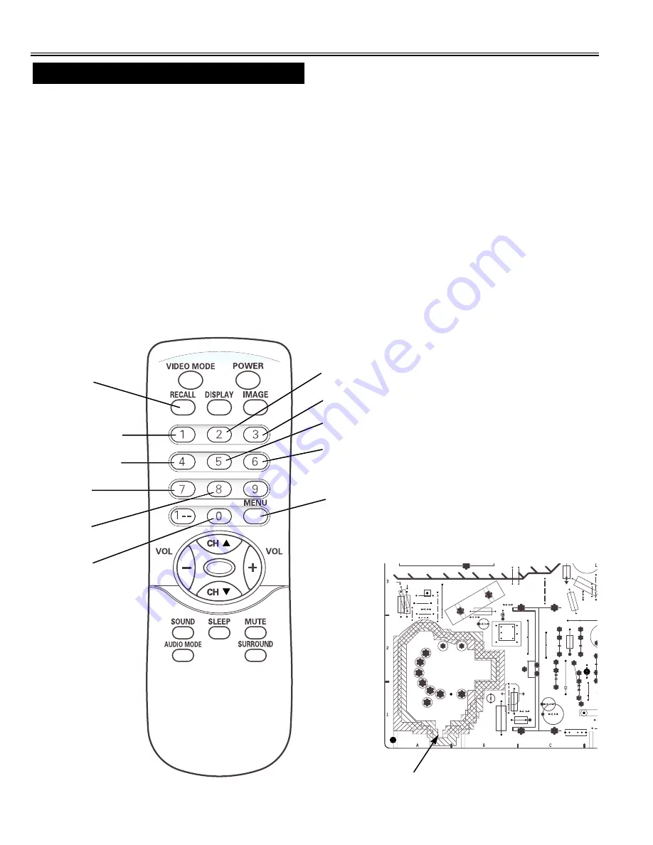
JXMRR
Red Bias -
Red Bias +
Green Bias -
Blue Bias +
Red Drive +
Blue Drive -
Blue Drive +
Green Bias +
Blue Bias -
Press the MENU button to exit
from service mode
Red Drive -
1. Receive a monochrome circular pattern.
2. Set the brightness and colour to normal, contrast to maximum.
3. Enter to the service mode.
4. Set each value of Item-16 RBIAS, 17 GBIAS, 18 BBIAS mode to 00. Set each value of Item-19 RDRIV, 21 BDRIV
mode to 63, 20 GDRIV to 08.
5. Select Item-22 mode to be one horizontal scanning line and turn the screen volume on the FBT to obtain just visible
one coloured line.
6. Press the 1 (Red Bias +), 4 (Red Bias -), 2 (Green Bias +), 5 (Green Bias -), 3 (Blue Bias +) or 6 (Blue Bias -)
button to adjust the brightness of each colour until a dim white line produced. Please see the control button alloca-
tions in this mode.
7. Select Item-23 DRV mode to enter the white balance adjusting mode.
8. Press the 7 (Red Drive +), RECALL (Red Drive -), 8 (Blue Drive +) or 0 (Blue Drive -) button alternately to
produce normal black and white picture.
9. Exit from the service mode.
10. Check for proper grey scale tracking at all brightness levels.
NOTE: If the grey scale adjustment is made after picture tube replacement, check the high voltage.
Items 16-23 GREY SCALE
Summary of Contents for TVP-2015AD
Page 24: ...Nov 04 Panoramic...