BA_PH_BSB-400-900_EN_44-21.docx
21
6
Installation and Connection
6.1
Check Delivery Conditions
Check the consignment for completeness and possible transport damage. In case of transport damage, please
keep the packaging and inform the shipping company and the manufacturer immediately! Later complaints can-
not be accepted.
6.2
Transport to the Installation Site
6.2.1
Transport of Models BSB 400 - 700
•
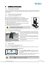
The machine is delivered upright bolted on a transport pallet.
•
The centre of gravity of the machine is approx. in the middle of the pallet.
•
Move between the pallet with a lift truck (see
Figure 7) and lift the
machine only a few centimetres and move it to the installation site.
•
Then remove the transport timbers, transport bolts and the lashing eye at-
tached to the machine column.
•
Now remove the machine from the pallet with a crane or similar suitable
lifting equipment and place it at the place of use.
•
Then follow the instructions in section
Danger of tipping over during transport!
Figure 7: Transport
6.2.2
Transport of Models BSB 800 - 900
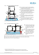
Figure 8: Crane eyelet
•
The machine is delivered lying on a transport pallet. First re-
move the transport timbers, transport bolts and the lashing
eye attached to the machine base or the machine column (de-
pending on the model).
•
Then it must be lifted from the pallet via the eyelet (
1
) with
the aid of a crane or a similar suitable lifting equipment and
erected vertically.
•
Now it can be placed on a lift truck with the crane and moved
to the installation site.
•
Then follow the instructions in section
6.3
Pre-Assembly
6.3.1
Pre-Assembly of Models BSB 400 - 700
The bandsaw models
BSB 400
-
BSB 700
are delivered completely assembled. Pre-assembly is not necessary.
6.3.2
Pre-Assembly of Models BSB 800 and 900
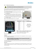
Figure 9: Attach protective cover
•
For the models
BSB 800
and
BSB 900.
the upper protective cover
must still be fitted and fastened via the holes (
B
) with the three
screws supplied.
•
In addition, the upper door must be inserted into the hinges and se-
cured with the locking screw above the lower hinge.
When installing the door, make sure that the pin of the door safety switch door safety switch
(refer to section
9.2) is inserted into the slot of the door.
1
B


