


BA_PH_680-100_EN_08-22.docx
35
10.2.1
Operating the Rip Fence
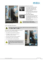
Important: For the operation of the rip fence, please also observe the hazard warnings in the
sections
4.5.4 und
The rip fence is used to feed the workpiece from the rear of
the machine (to the right of the saw blade).
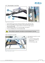
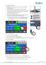
•
The rail (
4
) serves to guide of the rip fence (
1
).
•
The toggle lever (
6
) is used to fix and release
the rip fence on the ruler rod (
8
).
•
The rotary handle (
7
) is used for fine adjustment.
•
The adjusting screw (
5
) is used for locking.
•
The ruler (
9
) indicates the cutting dimension.
Warning! Danger of crushing between the work-
piece or the aluminium profile rail and the slide
table.
Figure 23: Operating the rip fence
4
6
8
1
5
9
7
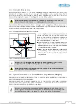
Figure 22: Fitting the rip fence
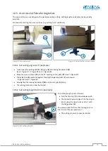
Set the aluminium profile rail for normal cuts:
•
Push the aluminium profile rail (
4
) as
far as it will go onto the two fixing
bolts (
3
) of the holding block. The
cross-section must look as shown in
the photo on the left.
•
Fix the aluminium profile rail by means
of the clamp lever (
2
). The fence (
1
) is
now ready for use.
Set aluminium profile rail for inclined saw blade:
•
Push the aluminium profile rail (4) onto
the holding block rotated by 90°. The
cross-section must look as shown in the
photo on the left .
Warning! Danger of crushing between
aluminium profile rail (4) and rip fence (1).
•
Fix the aluminium profile rail by means
of the clamp lever (
2)
.
2
4
3
1