INSTALLATION INSTRUCTIONS CM310
For Technical Support: www.panduit.com/resources/install_maintain.asp
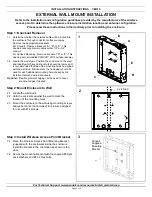
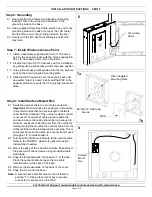
4.1 Run cable from the Telecommunications Grounding
Busbar (TGB) to the enclosure and attach to the
grounding stud on the base.
4.2 Using the supplied Grounding Cable, attach one end to
the grounding stud on the base (on top of TGB cable)
and the other end to the grounding stud on the door.
4.3 Secure with the #10 Split Lock Washers and #10-32 Hex
Nuts.
Step 4: Grounding
4
Grounding
Studs
4
Grounding
Studs
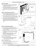
5.1 Attach mounting plate supplied with Cisco 1130 access
point to the enclosure base with the Cisco supplied #6-
32 x 1/4” flat head screws (note orientation)
5.2 Prepare the Cisco AP1130 access point for installation
by gently pushing the access point to the open position.
5.3 Line up the access point keyholes with the two keyhole
pads on the Cisco Supplied mounting plate.
5.4 Slide the WAP downward over the keyhole pads until
an audible “snap” is heard. Lightly pull the WAP in the
opposite direction to verify that it is properly locked into
place.
Step 5: Install Wireless Access Point
5a
5b
Cisco Supplied
Mounting Plate
#6-32x1/4” Flat Head
Screws
WAP
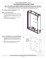
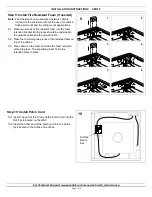
6.1 Run the network cable to and into the enclosure.
6.2 Terminate the Cat5e Jack Module to the network cable.
Refer to the PANDUIT website for jack termination
instructions if needed.
6.3 Mount the base of the 2 Position Surface Mount Box to
the back wall of the enclosure using provided double
sided tape.
6.4 Snap the terminated jack into position “1” of the box.
Place the network cable between the two cable
retention tabs on the back of the base.
6.5 Remove the breakout tab on the back of the cover.
6.6 Snap the cover onto the base.
Note: A second Cat5e Jack Module can be installed in
position “2” of the surface mount box to provide
access to the serial port on the WAP.
Step 6: Install Surface Mount Box
6 / 7
Surface
Mount
Box
Page 3 of 8
7.1 Insert one end of the 2' long Cat5e Patch Cord into the
RJ45 port located on the WAP.
7.2 Insert the other end of the patch cord into the Cat5e
jack located in the surface mount box.
Step 7: Install Patch Cord


