background image

© Panduit Corp. 2013 

OPERATING INSTRUCTIONS


CT-600-A


Page: 2 of 12 


CAUTION


AVAILABLE CRIMPING HEADS 

(Sold Separately) 

Make sure the air supply is “OFF” 

before installing the crimping heads 

and move the “SAFETY LOCK” lever 

to the “DOWN” position.


Panduit 

Part No. 

Terminal 

Type 

Wire 

Range 

CT-500CH 

Insulated 

22-14 

CT-520CH 

Insulated 

26-14 

CT-550CH 

Insulated 

22-10 

CT-570CH 

Non-Insulated 

22-10 


CRIMPING HEADS 

To install the crimping heads, turn the air supply “OFF”, move the “SAFETY LOCK” lever to the 
“DOWN” position and retract the two Lock Pins located at the head of the tool.  With the jaws wide open 
(rollers touching), slide the crimping head into the tool body and align the mounting holes in the tool 
frame.  Insert the Lock Pins and snap securely into place.  Wipe any excess oil from the crimping dies 
before using. 

Summary of Contents for CT-600-A

Page 1: ...TA DE CRIMPEO NEUM TICO INSTRUCCIONES DE OPERACI N ESPA OL 7 E mail techsupport panduit com www panduit com Technical Support 888 506 5400 ext 83255 Correo electr nico Latino America cs la panduit com...

Page 2: ...LY 3 OPERATING PRESSURE 3 CRIMPING TOOL OPERATION 3 MAINTENANCE 3 INSTALLATION OF FOOT PEDAL CONTROL FPC 600 A 4 INSTALLATION OF POSITIONING DEVICE PD 600 A 5 Maintenance of Positioning Device 6 TROUB...

Page 3: ...e used on live electric circuits Do not use with frayed abraded or cut air hose Failure to observe this warning can result in severe injury or death WARNING Do not remove the Safety Guard from the tip...

Page 4: ...14 CT 520CH Insulated 26 14 CT 550CH Insulated 22 10 CT 570CH Non Insulated 22 10 CRIMPING HEADS To install the crimping heads turn the air supply OFF move the SAFETY LOCK lever to the DOWN position a...

Page 5: ...exceed the optimum air pressure setting as this will cause premature tool wear CAUTION READ SAFETY PRECAUTIONS ON PAGE 1 BEFORE USING THIS TOOL CRIMPING TOOL OPERATION 1 Move the SAFETY LOCK to the D...

Page 6: ...STALLATION OF FOOT PETAL FPC 600 A 1 Position Actuator on back of CT 600 A and attach with thumbscrews 2 Assemble NPT male connector from Air Hose to pipe tee connection Connect Industrial quick disco...

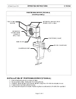
Page 7: ...h screws holding the Tool Clamp Blocks 3 Install CT 600 A between Tool Clamp Blocks away from CT 600 A s Actuation Lever 4 Tighten both Tool Clamp Block Screws 5 Use Swivel Clamp Arm to loosen Positio...

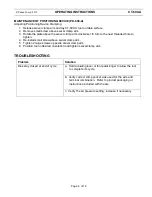
Page 8: ...aded hole to tighten 4 Re install small screw above swivel clamp arm 5 Tighten 2 large screws opposite swivel clamp arm 6 Position tool in desired orientation and tighten swivel clamp arm TROUBLESHOOT...

Page 9: ...E LA HERRAMIENTA DE CRIMPEO 9 MANTENIMIENTO 9 INSTALACI N DEL PEDAL DE CONTROL FPC 600 A 10 INSTALACI N DEL DISPOSITIVO DE POSICIONAMIENTO PD 600 A 11 Mantenimiento del dispositivo de posicionamiento...

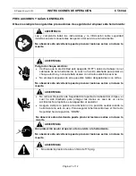
Page 10: ...os el ctricos activos No emplee mangueras de aire que est n ra das desgastadas o con cortes No observar esta advertencia puede provocar lesiones serias o incluso la muerte ADVERTENCIA No retire el Dis...

Page 11: ...CT 550CH Con aislaci n 22 10 CT 570CH Sin aislacion 22 10 CABEZALES DE CRIMPEO Para instalar los cabezales de crimpeo apague el suministro de aire OFF haga descender la palanca del CIERRE DE SEGURIDA...

Page 12: ...presi n de aire pues eso ocasionara el desgaste prematuro de la herramienta PRECAUCI N LEA LAS PRECAUCIONES DE SEGURIDAD EN LA P GINA 7 ANTES DE USAR ESTA HERRAMIENTA OPERACI N DE LA HERRAMIENTA DE CR...

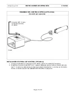
Page 13: ...ue el activador en el soporte de la CT 600 A y f jelo con tornillos tipo mariposa 2 Ensamble el conector macho NPT de desde la Manguera de Aire hacia la conexi n del tubo tipo T Conecte los aditamento...

Page 14: ...enta 3 Instale la CT 600 A entre los Bloques de Sujeci n de la Herramienta de modo que la palanca de activaci n quede alejada de la CT 600 A 4 Ajuste los dos tornillos del Bloque de Sujeci n de la Her...

Page 15: ...tar 4 Coloque el tornillo peque o de nuevo en su lugar sobre el brazo giratorio de sujeci n 5 Ajuste los dos tornillos grandes opuestos al brazo de sujeci n 6 Coloque la herramienta en la orientaci n...

Reviews: