3
Installation Guide
AT-OPUS-RX41
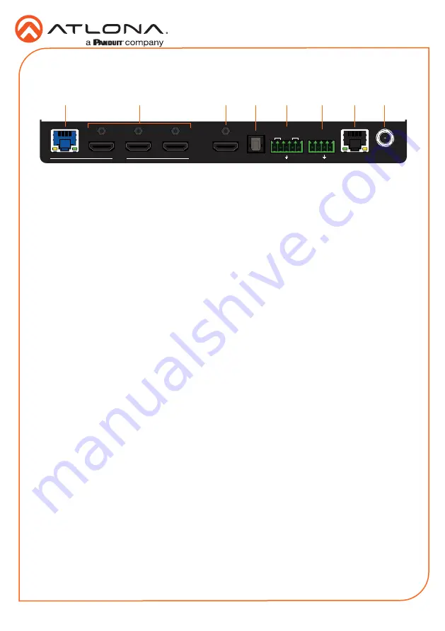
1
INPUT (HDBaseT)
Connect a category cable (CAT-5e or better) from this port to a compatible HDBaseT
transmitter. This category cable provides both data transfer and is used to power the AT-
OPUS-RX41.
2
INPUT (HDMI)
Connect an HDMI cable from each of these ports to an UHD/HD source.
3
OUTPUT (HDMI)
Connect an HDMI cable from this port to a display device.
4
OPTICAL
Connect a S/PDIF optical cable from this port to the TOSLINK port on an audio output
device.
5
HDBaseT RS-232 / IR
Connect a controller to this port to control a headend matrix (transmitter) over HDBaseT.
Refer to
for wiring information.
6
RS-232 / IR IN
Connect a controller or PC to control the AT-OPUS-RX41 through RS-232 or IR. Refer to
for wiring information.
7
LAN
Connect an Ethernet cable to this port to control the AT-OPUS-RX41 using the built-in web
server or to control a sink device using pass-through IP control.
8
DC 5V
Connect the optional locking 5 V DC power supply to this power receptacle.
OPTIONAL
RX TX
TX RX
INPUT
4
3
2
1
HDMI OUT
DC 5V
LAN
RX
S
TX
RS-232
IR IN
OPTICAL
HDBaseT
RS-232
IR
1
2
3
4
INPUT
INPUT
POWER
FW
AT-OPUS-RX41
OPUS
TM
Panel Descriptions
Rear
2
1
3
4
5
6
7
8


