background image

6

Installation Guide

AT-OPUS-RX41

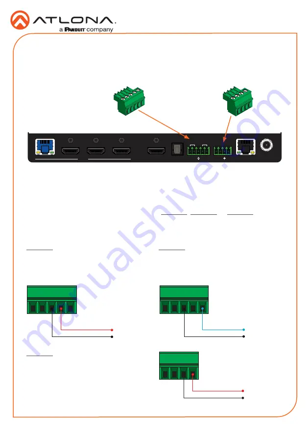
The 5-pin 

HDBaseT RS-232/IR

 port can be used to either control a display device or a source 

device over HDBaseT.  The 4-pin 

RS-232/IR IN

 port allows IR control of the AT-OPUS-RX41.  

Refer to the User Manual for more information.

1.  Locate the required captive screw connector (included in the box).
2.  Use wire strippers to remove a portion of the cable jacket.
3.  Remove at least 3/16” (5 mm) of insulation from each of the wires. 
4.  Insert the wires into correct terminal.  Refer to 

Figure 2.1

Figure 2.2

, or 

Figure 2.3

, below.

5.  Connect the captive screw block to the proper port.

IR Control

OPTIONAL

RX TX

TX RX

INPUT

4

3

2

1

HDMI OUT

DC 5V

LAN

RX

S

TX

RS-232

IR IN

OPTICAL

HDBaseT

RS-232

IR

1

2

3

4

INPUT

INPUT

POWER

FW

AT-OPUS-RX41

OPUS

TM

Figure 2.1


- Wiring the 5-pin HDBaseT 

RS-232/IR captive screw block to have a 

controller at the viewing location send IR 

commands over HDBaseT to an IR emitter

Figure 2.3


- Wiring the 4-pin HDBaseT RS-

232/IR IN captive screw block to control the 

AT-OPUS-RX41 over IR.

Figure 2.2


- Wiring the 5-pin HDBaseT 

RS-232/IR captive screw block to send IR 

commands out over an IR emitter, from 

a control system placed remotely at the 

transmitter side.

TX

GND

to control system

S

to control system

GND

RX

GND

to IR emitter

Summary of Contents for ATLONA Opus AT-OPUS-RX41

Page 1: ...R and RS 232 signals over HDBaseT allows a control system connected to the OPUS RX41 to select inputs on the matrix or control its sources and allows the matrix to control the local room display A handheld IR remote control is included for power and input selection on the OPUS RX41 Advanced HDMI Audio Return Channel ARC routes audio from a smart TV to both the local TOSLINK connection as well as H...

Page 2: ...tive input will be indicated with a solid green light 3 POWER This LED indicator glows solid green when the unit is powered 4 INPUT Press and release this button to cycle through each of the four inputs Each LED indicator corresponds to each of the numbered inputs on the rear panel of the unit The INPUT LED indicators will indicate the active input with a solid green light 5 FW Connect a USB to mi...

Page 3: ...port to control a headend matrix transmitter over HDBaseT Refer to RS 232 Control page 5 and IR Control page 6 for wiring information 6 RS 232 IR IN Connect a controller or PC to control the AT OPUS RX41 through RS 232 or IR Refer to RS 232 Control page 5 and IR Control page 6 for wiring information 7 LAN Connect an Ethernet cable to this port to control the AT OPUS RX41 using the built in web ser...

Page 4: ...s this button to toggle audio muting on the HDMI OUT port 1 4 2 3 Front Panel LED Indicators The LED indicators on both the front and rear of the unit provide basic information on the current status of the unit 1 2 3 4 Description Solid green The input is the active input Off The input is not selected POWER Description Blue backlight Unit is powered Off Unit is not powered IP MODE Description Blue...

Page 5: ...OPUS RX41 NOTE Typical DB9 connectors use pin 2 for TX pin 3 for RX and pin 5 for ground On some devices functions of pins 2 and 3 are reversed RS 232 Control 1 Locate the required captive screw connector included in the box 2 Use wire strippers to remove a portion of the cable jacket 3 Remove at least 3 16 5 mm of insulation from each of the wires 4 Insert the wires into correct terminal Refer to...

Page 6: ...re 2 3 below 5 Connect the captive screw block to the proper port IR Control OPTIONAL RX TX TX RX INPUT 4 3 2 1 HDMI OUT DC 5V LAN RX S TX RS 232 IR IN OPTICAL HDBaseT RS 232 IR 1 2 3 4 INPUT INPUT POWER FW AT OPUS RX41 OPUSTM Figure 2 1 Wiring the 5 pin HDBaseT RS 232 IR captive screw block to have a controller at the viewing location send IR commands over HDBaseT to an IR emitter Figure 2 3 Wiri...

Page 7: ... RS 232 IR IN port to control the AT OPUS RX41 Both RS 232 and IR protocols are supported Refer to RS 232 Control page 5 and IR Control page 6 for wiring information 7 Connect an Ethernet cable to the LAN port to control the AT OPUS RX41 using the built in web server or to control a sink device using pass through IP control 8 OPTIONAL Connect the included 5 V DC power supply Atlona part no AT PS 5...

Page 8: ...nce AMS has been setup following the instructions below 1 Open a browser on the same network as AMS 2 0 and go to the IP of AMS 2 0 View the AMS 2 0 installation instructions on how to find the IP of the software if necessary 2 Enter the login information on the AMS 2 0 web page then click the Login button 3 View the AT OPUS RX41 manual for routing and configuration information AMS 2 0 IP Configur...

Page 9: ...de of the enclosure with one set of holes on the mounting bracket 3 Use the screws from Step 1 to attach the mounting bracket 4 Repeat steps 1 and 2 to attach the second mounting bracket to the opposite side of the unit 5 Mount the unit to a flat surface using the oval shaped holes on each mounting bracket If using a drywall surface a 6 drywall screw is recommended 1 2 3 4 INPU T INPU T PO WER FW ...

Page 10: ...10 Installation Guide AT OPUS RX41 Notes ...

Page 11: ...11 Installation Guide AT OPUS RX41 Notes ...

Page 12: ... Actual products product images and online product images may vary from images shown here Toll free US International atlona com 877 536 3976 41 43 508 4321 English Declaration of Conformity Chinese Declaration of Conformity 中国RoHS合格声明 The English version can be found under the resources tab at https atlona com product at opus rx41 由SKU列出於 https atlona com about us china rohs The terms HDMI HDMI Hi...

Reviews: