Panduit ATLONA AT-UHD-SW-510W-KIT Installation Manual Download Page 9

9

Installation Guide

AT-UHD-SW-510W

Installation

1. 

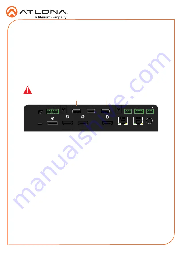
Connect a USB-C cable from a source to the 

USB-C (1)

 port.

2. 

Connect a DisplayPort cable from a source to the 

DP IN (2)

 port.

3. 

Connect up to two UHD/HD sources, using HDMI cables, to the 

HDMI IN (3)

 and 

HDMI IN 

(4)

 ports.

4. 

Connect an HDMI cable from the 

HDMI OUT

 port to a UHD/HD display.

5. 

Connect up to two USB wireless antenna modules to the identified 

USB (WiFi)

 ports, below. 

Two USB wireless antennas are included.  

WiFi

 (1) supports Google Cast™ and Apple 

AirPlay®.  The 

MIRACAST 

port (2) only supports Miracast™.  The 

AUX

 port is reserved for 

obtaining the IP address of the unit.  Refer to 

Obtaining the IP Address

 on page 10 for more 

information. 


6. 

Connect the relay leads from the control motors of the projection screen, blinds, or curtains, 
to the relay outputs to the 

RELAY

 port, using the included 3-pin captive screw connector.  

Use a 48 V DC relay with no more than 1 A current draw.

7. 

Connect a trigger device, such as an occupancy sensor switch, to the 

TRIGGER I/O

 port.  

A 4-pin captive screw connector is required.  Voltages from 3 to 30 V are supported.

8. 

Connect a 3.5 mm analog audio cable from an analog source to the 

AUDIO IN

 port. 

This audio source can be used to embed analog audio on any of the input sources.

9. 

Connect an Ethernet cable from the 

LAN

 port to the Local Area Network (LAN).

10.  Connect an Ethernet cable from the 

HDBaseT

 port to an HDBaseT receiver unit, such as 

the AT-UHD-EX-100CE-RX-PSE.

11.  Connect the included green 5-pin captive screw connector to the 

AUDIO OUT

 connector.

12.  Connect the included power supply to the 

DC 24V

 connector and connect the power cord 

to an available electrical outlet.

13.  Follow the on-screen instructions to complete the set-up procedure.

LAN

DC 24V

HDBaseT OUT

HDMI OUT

HDMI IN

DP IN

USB-C IN

2

3

4

1

RELAY

RS-232

TRIGGER I/O

MIRACAST

WiFi

AUX

AUDIO

 OUT

L

R

IN

USB

+

C1 COM C2

RX

P

TX

+

+

US

B

US

B

US

B

2

1

IMPORTANT

: Only use Atlona Wi-Fi USB modules.  Other Wi-Fi modules may 

not be supported by this product. 

Resetting the Factory-Default Settings

Press and hold the 

DISPLAY

 button for 15 seconds to reset the AT-UHD-SW-510W to factory-

default settings.  Note that the AT-UHD-SW-510W will be placed in DHCP mode, as part of the 
reset procedure.

Summary of Contents for ATLONA AT-UHD-SW-510W-KIT

Page 1: ...play control capability both applicable to wired and wireless source connections Additionally the SW 510W can be integrated with an occupancy sensor to automatically power up the unit and display avai...

Page 2: ...the IP address of the AT UHD SW 510W on the connected display 4 POWER Press and hold this button for five seconds to power off the AT UHD SW 510W To power on the unit disconnect and reconnect the pow...

Page 3: ...Use the included captive screw connector to connect an RS 232 controller or automation system 7 USB C Connect a USB C cable from this port to a USB C source 8 DP IN Connect a DisplayPort device to th...

Page 4: ...connectors NOTE Typical DB9 connectors use pin 2 for TX pin 3 for RX and pin 5 for ground On some devices functions of pins 2 and 3 are reversed RS 232 GND RX TX The AT UHD SW 510W provides the abili...

Page 5: ...n or rebooted C1 and C2 are set to the Normally Open NO state C2 COM C1 Trigger The TRIGGER I O port allows voltage controlled devices such as an occupancy sensor to be connected to the AT UHD SW 510W...

Page 6: ...ce Single unit rack installation 1 Attach the included small rack ear sold separately to one side of the AT UHD SW 510W using the included screws 2 Attach the included longer rack ear sold separately...

Page 7: ...s on the mounting plate should face upward 3 Turn the attached units over and install the rack ears sold separately to one side of each enclosure using the included screws US B C DP HD M I 3 HD M I 4...

Page 8: ...els on the mounting plates should face upward 3 Mount the unit using the circular holes on each mounting plate If using a drywall surface a 6 drywall screw is recommended Mounting screws are not inclu...

Page 9: ...pin captive screw connector is required Voltages from 3 to 30 V are supported 8 Connect a 3 5 mm analog audio cable from an analog source to the AUDIO IN port This audio source can be used to embed a...

Page 10: ...Configuration Connection Diagram Press and hold the INPUT button for approximately 15 seconds Release the INPUT button All the front panel LED indicators will begin to flash then the unit will reboot...

Page 11: ...4 3 The AT UHD SW 510W Login page will be displayed 4 Enter the following information on the Login page Login admin Password Atlona 5 Click the Login button 6 Refer to User Manual for detailed operati...

Page 12: ...arging my USB device Check that the USB cable is not damaged and provides a secure connection between the AT UHD SW 510W and the USB device Check the voltage rating of the connected device to make sur...

Page 13: ...13 Installation Guide AT UHD SW 510W Notes...

Page 14: ...14 Installation Guide AT UHD SW 510W Notes...

Page 15: ...15 Installation Guide AT UHD SW 510W Notes...

Page 16: ...ona Inc All other brand names and trademarks or registered trademarks are the property of their respective owners Pricing specifications and availability subject to change without notice Actual produc...

Reviews: