


Operation &
Maintenance Manual
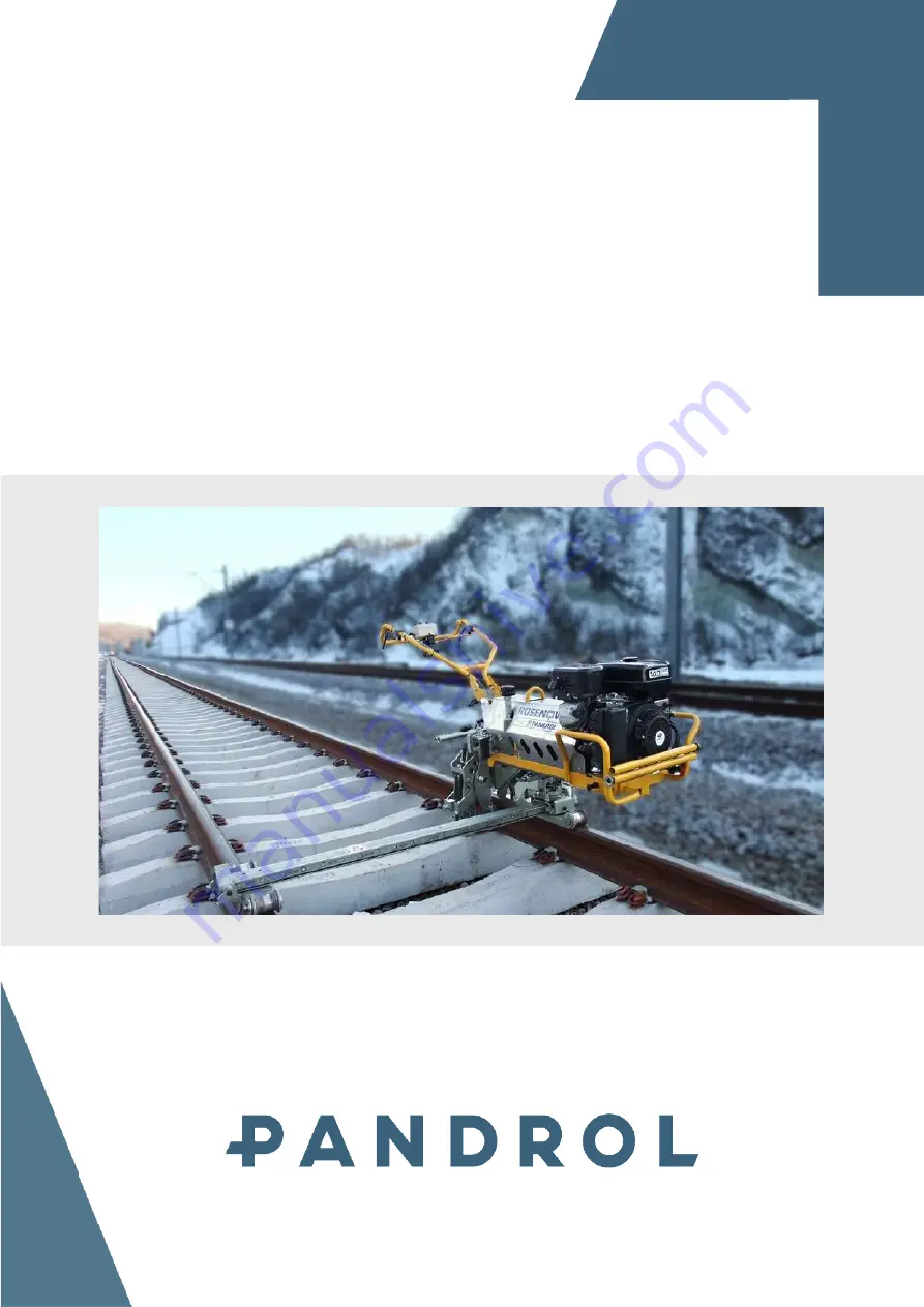
Rosenqvist CD200
Issue date:2016-11-11
Dokument ID:ENG_OMM_CD200
Revision:P05
Original instructions
Pandrol AB, Hyggesvägen 4, 824 34 Hudiksvall, Sweden
Phone +46 650-16505, www.rosenqvistrail.com, [email protected]
The PANDROL Rosenqvist CD200 is a powerful machine used for rail fastening operations. Ensure proper maintenance and safe use of this equipment by downloading the Operation & Maintenance Manual for free from manualshive.com. Keep your CD200 in top condition with this essential manual.
Operation &
Maintenance Manual
Rosenqvist CD200
Issue date:2016-11-11
Dokument ID:ENG_OMM_CD200
Revision:P05
Original instructions
Pandrol AB, Hyggesvägen 4, 824 34 Hudiksvall, Sweden
Phone +46 650-16505, www.rosenqvistrail.com, [email protected]


