background image

2

CONTENTS

IMPORTANT SAFETY INSTRUCTIONS  ........................................................................................................................................ 3
PREFACE ...................................................................................................................................................................................... 4
FEATURES .................................................................................................................................................................................... 4
PRECAUTIONS ............................................................................................................................................................................. 5
MAJOR OPERATING CONTROLS AND THEIR FUNCTIONS  ...................................................................................................... 6
INSTALLATION ............................................................................................................................................................................. 9
SYSTEM INFORMATION  .............................................................................................................................................................. 10
SPECIFICATIONS ......................................................................................................................................................................... 11
STANDARD ACCESSORY ............................................................................................................................................................ 11
MAJOR OPTIONAL UNITS AND ACCESSORIES ......................................................................................................................... 11

The serial number of this product may be found on the bot-
tom of the unit.
You should note the serial number of this unit in the space
provided and retain this book as a permanent record of your
purchase to aid identification in the event of theft.

Model No.

WV-CU550CJ

Serial No.

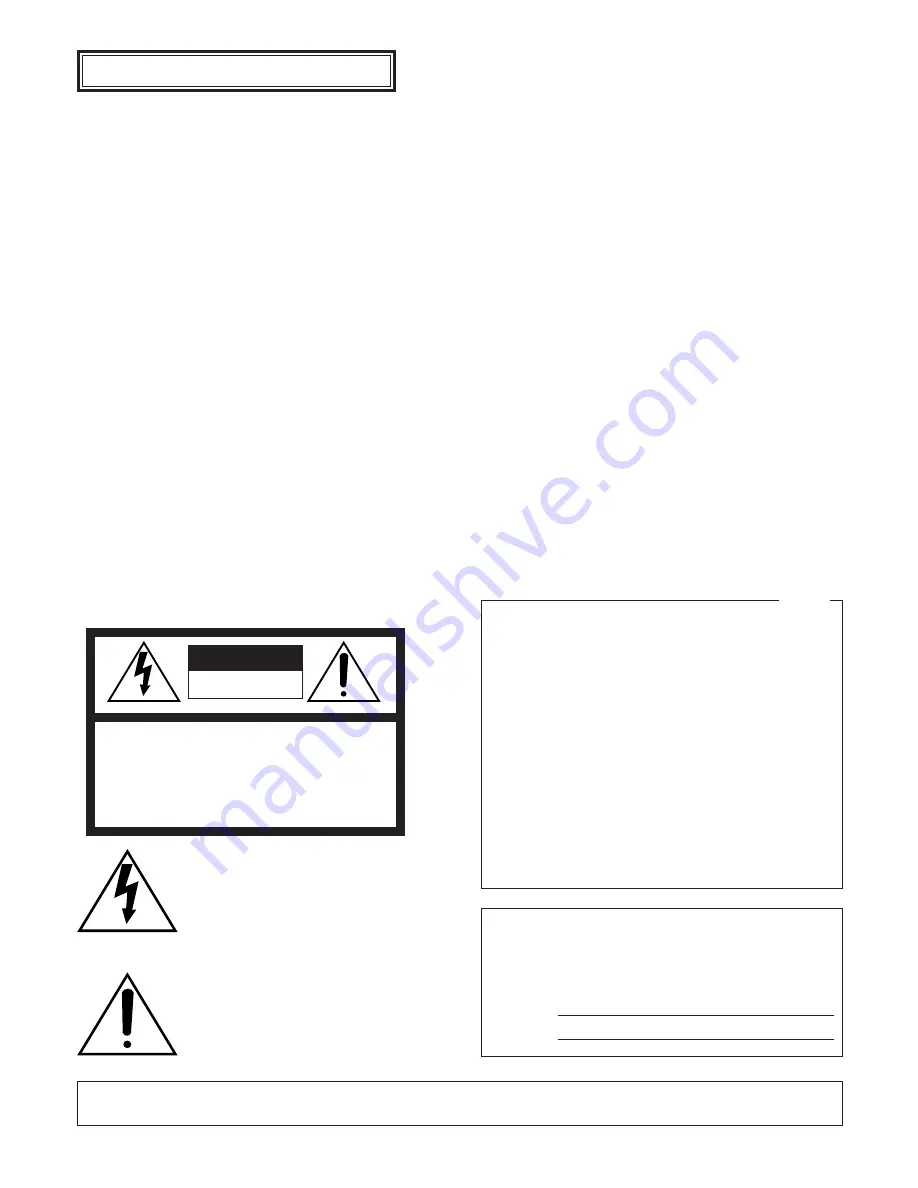
Caution:

Before attempting to connect or operate this product,
please read the label on the bottom.

NOTE: This equipment has been tested and found to com-
ply with the limits for a Class A digital device, pursuant to
Part 15 of the FCC Rules. These limits are designed to pro-
vide reasonable protection against harmful interference
when the equipment is operated in a commercial environ-
ment. This equipment generates, uses, and can radiate
radio frequency energy and, if not installed and used in
accordance with the instruction manual, may cause harmful
interference to radio communications.
Operation of this equipment in a residential area is likely to
cause harmful interference in which case the user will be
required to correct the interference at his own expense.

FCC Caution: To assure continued compliance, (example -
use only shielded interface cables when connecting to com-
puter or peripheral devices). Any changes or modifications
not expressly approved by the party responsible for compli-
ance could void the user’s authority to operate this equip-
ment.

For U.S.A

WARNING:

To reduce the risk of fire or electric shock, do not expose this appliance to rain or moisture.

The lightning flash with arrowhead symbol,
within an equilateral triangle, is intended to
alert the user to the presence of uninsulated
"dangerous voltage" within the product's
enclosure that may be of sufficient magni-
tude to constitute a risk of electric shock to
persons.

The exclamation point within an equilateral
triangle is intended to alert the user to the
presence of important operating and mainte-
nance (servicing) instructions in the litera-
ture accompanying the appliance.

CAUTION: TO REDUCE THE RISK OF ELECTRIC SHOCK,

DO NOT REMOVE COVER (OR BACK).

NO USER-SERVICEABLE PARTS INSIDE.

REFER SERVICING TO QUALIFIED SERVICE PERSONNEL.

CAUTION

RISK OF ELECTRIC SHOCK

DO NOT OPEN

SA 1965

SA 1966

ENGLISH VERSION

Summary of Contents for WVCU550CJ - SYSTEM CONTROLLER

Page 1: ...ual for future use Model No WV CU550CJ System Controller Operating Instructions ALARM ACK RESET AUX DEC 1CAM INC 1CAM STOP SLOW ESC SET MON CAM WIDE FAR AF ZOOM TELE FOCUS NEAR RESET IRIS 1 2 3 4 5 6 7 8 0 9 CLOSE OPEN 1 2 BACK SEQ FORWARD SEQ ALT BUSY F1 F2 F3 F4 System Controller WV CU CJ 550 ENGLISH FRANÇAIS ...

Page 2: ...ications Operation of this equipment in a residential area is likely to cause harmful interference in which case the user will be required to correct the interference at his own expense FCC Caution To assure continued compliance example use only shielded interface cables when connecting to com puter or peripheral devices Any changes or modifications not expressly approved by the party responsible ...

Page 3: ... outlet consult an electrician for replacement of the obsolete outlet 10 Protect the power cord from being walked on or pinched particularly at plugs convenience receptacles and the points where they exit from the apparatus 11 Only use attachments accessories specified by the manufacturer 12 Use only with the cart stand tripod bracket or table specified by the manufacturer or sold with the apparat...

Page 4: ... to any one of 16 monitors Remote control of up to 128 cameras and auxiliary equipment by using optional receivers and accessories including 1 Remote control of Pan Tilt Head and Camera Housing 2 Remote control of Motorized Zoom Lenses Focus Zoom and Iris 3 Remote control of camera settings including Electronic Sensitivity Enhancement Electronic Shutter Electronic Zoom and more Selection of variou...

Page 5: ...r try to operate it in wet areas Take immediate action if the appliance becomes wet Turn the power off and refer servicing to qualified ser vice personnel Moisture may damage the appliance and also cause electric shock Do not use strong or abrasive detergents when cleaning the appliance body Use a dry cloth to clean the appliance when it is dirty When the dirt is hard to remove use a mild detergen...

Page 6: ...AF ZOOM TELE ESC SLOW ALT BACK SEQ ACK RESET FORWARD SEQ DEC 1CAM AUX INC 1CAM STOP 2 1 F3 F4 1 2 3 4 5 6 7 8 9 MON 0 CAM CLOSE OPEN IRIS PRESET FAR FOCUS NEAR q w r t y i 0 3 4 5 6 7 8 9 2 1 2 o e u 3 1 0 CONTROLLER CONTROLLER UNIT No 1 8 MODE DATA TERM ON ON OUT OFF OFF IN 54 3 2 1 0 9 8 7 6 4 5 6 7 8 9 Rear View ...

Page 7: ...ton AF PRESET This button in combination with the Numeric keys is used to move the selected camera to a pre set position in a system equipped with the specified cameras AF Pressing this button will automatically set the lens focus of a specified camera 3 Camera Set Key CAM SET CAM Used for camera selection To select a camera enter the desired camera number with the Numeric keys and then press the ...

Page 8: ...d from the step that was previously paused by pressing the Stop button 3 Alarm Acknowledge and Reset Button ACK RESET This button cancels an activated alarm To cancel an alarm first select the alarmed monitor s then press the ACK RESET button once for alarm acknowledgment the indicator on the button blinks rapidly and finally press it again for alarm reset the indicator goes off After an alarm ack...

Page 9: ...l on the controller shown below Refer to the Operating Instructions of WJ FS616 Series for further details Note Locate the System Controller in a level place INSTALLATION ALARM ACK RESET AUX DEC 1CAM INC 1CAM STOP SLOW ESC SET MON CAM WIDE FAR AF ZOOM TELE FOCUS NEAR RESET IRIS 1 2 3 4 5 6 7 8 0 9 CLOSE OPEN 1 2 BACK SEQ FORWARD SEQ ALT BUSY F1 F2 F3 F4 System Controller WV CU CJ 550 ...

Page 10: ...y pressing the STOP SLOW button is enabled only when FST mode is selected The above function is available in a system that includes the following equipment WJ SX550 Series Matrix Switcher CPU Ver 6 00 or later Control Ver 6 00 or later WV PB5548 Data Board Ver 6 00 or later Version Information WJ SX550 Series Matrix Switcher The onscreen display indicates the version in Cold Start or Normal Start ...

Page 11: ...oster On Off Camera On Off Pan Tilt Manual Pan Right Left Manual Tilt Up Down Auto Pan On Off Random Pan On Off Preset Home Auxiliary Switch AUX 1 and 2 On Off Unit Number 1 to 8 Ambient Operating Temperature 10 C to 50 C 14 F to 122 F Ambient Operating Humidity Less than 90 Dimensions 370 mm W x 129 mm H x 221 mm D 14 9 16 W x 5 1 8 H x 8 11 16 D Weight 2 2 kg 4 8 lbs Weight and dimensions indica...

Page 12: ... Km 9 5 San Gabriel Industrial Park Carolina Puerto Rico 00985 809 750 4300 Panasonic Security and Digital Imaging Company A Division of Matsushita Electric Corporation of America Executive Office One Panasonic Way 3E 7 Secaucus New Jersey 07094 Regional Offices Northeast One Panasonic Way Secaucus NJ 07094 201 348 7303 Southern 1225 Northbrook Parkway Suite 1 160 Suwanee GA 30024 770 338 6838 Mid...

Reviews: