


Operating Instructions
Network Camera
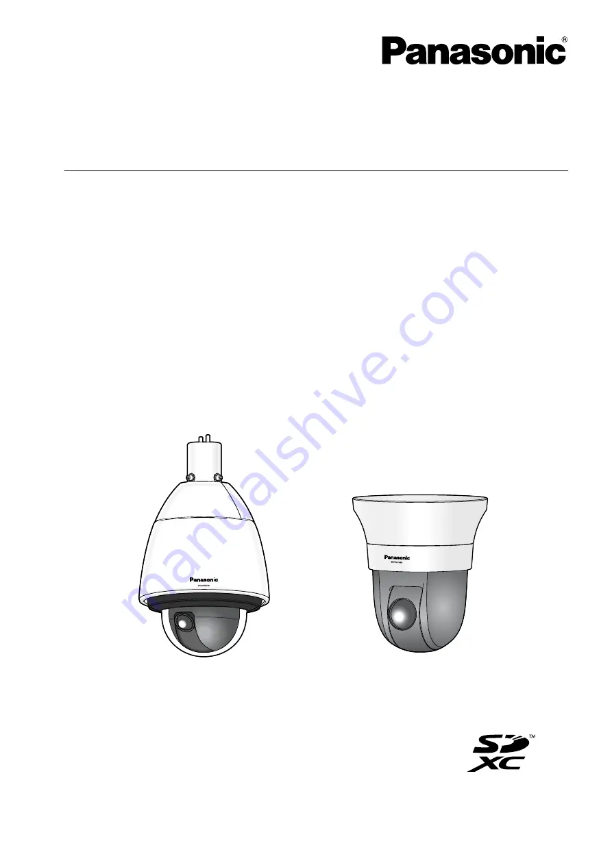
Model No.
WV-SW598
WV-SW598J
WV-SC588
WV-SW397
WV-SW397A
WV-SW397J
WV-SW397AJ
WV-SC387
WV-SC588
WV-SW598
Before attempting to connect or operate this product, please read these instructions
carefully and save this manual for future use.
The model number is abbreviated in some descriptions in this manual.


