

3
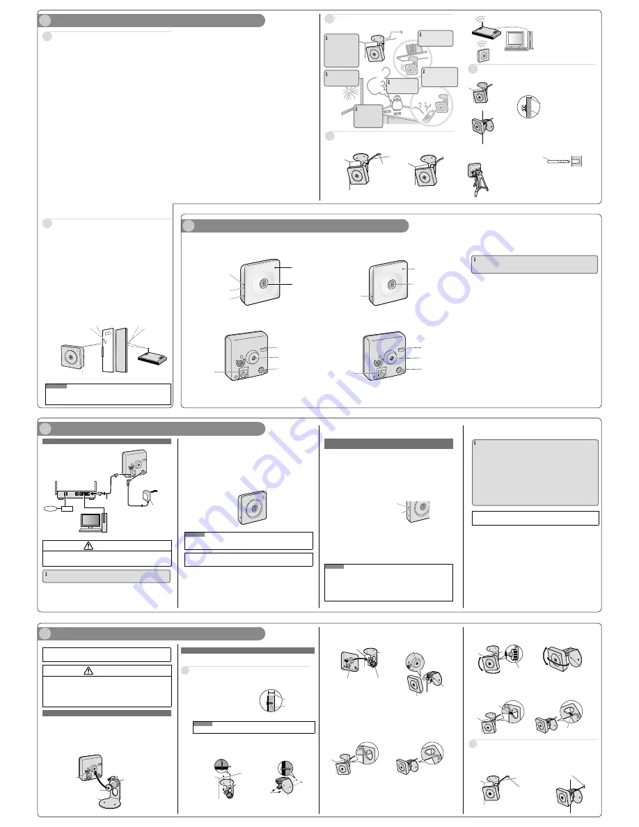
Connections
3
Loosen the position lock of the flexible stand, and turn the mounting
screw to attach the camera.
4
Pass the cord of the AC adaptor (accessory) and LAN cable (locally
procured) through the hole of the flexible stand, and then connect
them to the camera while referring to "3 Connections".
1
Connect the LAN cable to the camera and the router.
When connecting the camera to a wireless LAN, refer to “When connecting the cam-
era using a wireless LAN”.
1
Check the installing place
2
Major operating controls
Determining the mounting position
Precautions for Installation
About the range of use for wireless communication
(BL-VP104W/BL-VP104WE/BL-VP104WU)
¢
Installing the camera on the wall
Make sure the flexible stand is firmly mounted on a beam of wood (25 mm
{31/32 inches} and greater) etc. When there is no beam, apply a board on
the other side of the wall to make sure the camera does not drop.
When mounting on a mortar or concrete surface
Prepare anchors for 4 mm {5/32 inches} diameter screws for mounting.
Mortar walls break easily when drilling. Be careful of pieces of mortar
which may become loose and fall.
1. Place the flexible stand on the wall where you plan to mount the flexible
stand and mark the points where you are going to make holes.
2. Make holes with an electric drill. Insert anchors (locally procured)
into the holes and push them inside the holes with a hammer.
3. Mount the flexible stand using the screws.
Drill for concrete (in case of
tile, use a drill for tile)
Determining how to mount the camera
¢
Tripod Mount
It is also possible to mount the camera on a standard tripod stand (locally
procured).
Beam of wood
At least 25 mm {31/32 inches}
Panasonic assumes no responsibility for injuries or property damage resulting
from failures arising out of improper installation or operation inconsistent with
this documentation.
This camera is designed to be used indoors.
This camera is not operable outdoors.
Do not expose this camera to direct sunlight for hours and do not install the product
near a heater or an air conditioner. Otherwise, it may cause deformation, discoloration
and malfunction. Keep this camera away from water and moisture.
Do not place this product in the following places:
Locations where it may get wet from rain or water splash
Locations where a chemical agent is used such as a swimming pool
Locations subject to humidity, dust, steam and oil smoke
Locations that have a specific environment that is subject to an inflammable atmosphere or solvents
Locations where a radiation, an X-ray, a strong radio wave or a strong magnetic field
is generated
Locations where corrosive gas is produced, Locations where it may be damaged by
briny air such as seashores
Locations where the temperature is not within the specified range (0 °C to +40 °C
{32 °F to +104 °F}).
Locations subject to vibrations (This product is not designed for on-vehicle use.)
Locations subject to condensation as the result of severe changes in temperature
Be sure to remove this product if it is not in use.
Before installation
When this camera is mounted on a wooden wall, use the wood screws (accessory).
Screws to be used for other materials are not provided. Prepare the screws according to
the material, structure, strength and other factors of the mounting area and the total
weight of objects to be mounted.
Ensure that the mounting surface, anchor and screws are sufficiently strong.
Do not mount this product on a plaster board or a wooden section because they are
too weak. If this product is unavoidably mounted on such a section, the section shall
be sufficiently reinforced.
Design and engineer the power supply system to turn on/off the power
of this product.
The product has no power switch. When installing the product, use a power supply
device equipped with the ON-OFF switch. Alternatively you can simply disconnect the
AC adaptor from the power supply when performing installations.
About the network connection
When connecting to a network using the network cable of this product, observe the fol-
lowing. When wiring for the network, design and engineer not to be affected by thunder.
Screw tightening
The screws must be tightened with an appropriate tightening torque according to
the material and strength of the installation area.
Do not use an impact driver. Use of an impact driver may damage the screws or
cause tightening excessively.
When a screw is tightened, make the screw at a right angle to the surface. After tightening
the screws, perform checks to ensure that the tightening is sufficient enough so that there
is no movement or looseness.
Procure fixing screws separately.
The screws that secure this product are not supplied. Prepare them according to the
material and strength of the area where the product is to be installed.
Required pull-out capacity of a single screw is 196 N {44.06 lbf} or more.
Do not remove or loosen the internal camera screws.
Do not loosen the internal camera screws. Otherwise, water exposure may cause
damage or malfunction of camera, or camera dropping may result in injury.
Radio disturbance
When this product is used near TV/radio antenna, strong electric field or magnetic field
(near a motor, a transformer or a power line), images may be distorted and noise
sound may be produced.
Router
When connecting this product to the Internet, use a broadband router with the port for-
warding function (NAT, IP masquerade). Refer to the Operating Instructions (included in
the CD-ROM) for further information about the port forwarding function. Configure the
wireless settings of the camera to match the wireless settings of the router. For infor-
mation on the wireless settings of the router, refer to the operating instructions included
with your wireless router.
Time & date setting
It is necessary to set the time & date before putting this product into operation. Refer to
the Operating Instructions on the provided CD-ROM for descriptions of how to perform
the settings.
About the [INITIAL SET] button
After turning off the power of the camera, turn on the power of the camera while holding down
this button, and wait for around 5 seconds or more without releasing this button. Wait around
3 minutes after releasing the button. The camera will start up and the settings including the
network settings will be initialized. Before initializing the settings, it is recommended to write
down the settings in advance. The initialization will be complete when the power indicator
stops blinking orange and lights off. Note that the CRT key (SSL encryption key) used for the
HTTPS protocol will not be initialized.
IMPORTANT
Do not turn off the power of the camera during the process of initialization. Otherwise,
it may fail to initialize and may cause malfunction.
About the POWER indicator and the WIRELESS indicator (WPS indicator)
For more information, see Configure the basic settings [Basic] in the Operating Instructions
(included in the CD-ROM).
<BL-VP104W>
Power indicator
Lens
<Rear View>
INITIAL SET button
WIRELESS button
(WPS button)
WIRELESS indicator
(WPS indicator)
<BL-VP101/BL-VP104>
WAN
4 3 2 1
LAN
Router
Internet
Modem
PC
LAN cable
(Cat-5 straight cable)
AC adaptor
To the
power
outlet
When connecting the camera to your router
IMPORTANT
Use a 4-pair UTP/STP cable.
(This illustration represents BL-VP101.)
<Front view>
(This illustration represents BL-VP104W.)
When using a wireless connection, con-
figure the wireless settings for the cam-
era and the wireless router before install-
ing the camera.
Confirm in advance that the camera can
connect with the wireless router from its
installed place. Refer to “3 Connections”
for further information.
Do not use this product in the following areas or locations.
(It may cause interference to radio communications or malfunction.)
Indoor areas that have specified radio stations or mobile communications
equipment
Locations near microwave ovens or Bluetooth devices
Indoors areas that use antitheft devices or 2.4 GHz frequency devices such as
POS systems
Change the installation location of the camera when there are materials or
objects such as the following between the camera and a wireless router.
(When there are materials or objects that are difficult for radio waves to pass through in
the installation area, wireless transmission may fail or the transmission speed may
become slower.)
(When there are materials or objects that reflect radio waves in the installation area,
wireless transmission may fail or the transmission speed may become slower due to
interference from reflected radio waves.)
A metallic door or shutter
A wall with an insulation material that contains aluminum foil
A wall made of concrete, stone or brick
Several walls separated by open space
A wall made of tin
A steel shelf
Fireproof glass
A steel door
A reinforced concrete wall
Internal Antenna (Both sides)
Note
When two or more radio routers and radio interference exist, radio may become being hard
to be connected or transmission speed may become remarkably slow. In that case, it may
be necessary to change the channel of a radio router or to rearrange wireless applications.
Note
The camera operates in wireless mode when the camera is turned on without the LAN
cable connected or with the power of the router turned off. Recheck the LAN cable con-
nection and the power to the router, and then turn the camera on or off.
After connecting the camera, refer to “Configure the settings of the
camera” (leaflet) and perform the camera settings.
Confirm the status of the wireless connection on the [Status] tab of the “Wireless” page.
<Front view>
Power indicator
Lens
<Rear View>
INITIAL SET button
After connecting the camera, refer to “Configure the settings of the
camera” (leaflet) and perform the camera settings.
Before installing the camera, check that the camera settings have been
completed. Refer to “Configure the settings of the camera” (leaflet).
(This illustration represents BL-VP101.)
When connecting the camera using a wireless LAN
(BL-VP104W/BL-VP104WE/BL-VP104WU)
IMPORTANT
WPS function is unavailable when the wireless router is set to shared key authentication.
When the wireless router or other devices are set to use the ESS-ID stealth function
(hidden SSID), the WPS function is unavailable.
During the configuration of WPS setting, another wireless device may be temporarily
caused interference by the wireless router.
If the wireless router is configured to use the MAC address filtering feature, the WPS
function is unavailable. Check the settings of the wireless router.
If the settings for the WPS function are performed when no wireless devices to be
connected to the wireless network, etc. the configuration will be automatically cancelled
after 2 minutes. (Check the wireless router in use before configuration.)
The auto setup of the WPS function may be unavailable if there are multiple Registrars
(wireless router which have the WPS function on) on the same network.
If you do not use the WPS function of the wireless router, we recommend that you turn
OFF your wireless router WPS feature.
Determining how to wire the cable
It is necessary to make a hole in the ceiling or wall to pass the cables through.
Make a hole in diameter.
Hole for cables
IMPORTANT
Do not mount this product on
a plaster board or a wooden
section because they are too
weak. If this product is
unavoidably mounted on such
a section, the section
shall be sufficiently reinforced.
IMPORTANT
Do not install this by products
that generates a strong radio
wave or a strong magnetic field.
IMPORTANT
Do not install on
locations subject
to humidity and oil
smoke.
IMPORTANT
Do not install near the
strong light source.
IMPORTANT
Do not install near
any heat sources.
IMPORTANT
Do not install this on locations
subject to vibrations.
LAN port
AC adaptor cord hook
Stand/Tripod mounting
hole
DC IN jack
LAN port
Use the camera’s WIRELESS button (WPS button) to automatically perform wireless settings.
1
Turn on the camera without connecting the LAN cable to enable
the wireless settings.
After the internal initial operations are performed, the power indicator stops blinking
orange and lights orange. The power indicator lights orange and the camera starts up in
wireless LAN mode about 90 seconds after the camera was turned on.
2
Select ON for the WPS function (Push-button method (PBC)) on
the wireless router. (For more information, refer to the operating
instructions included with your wireless router.)
3
Press and hold down the WIRELESS button for a second or more
until the WIRELESS indicator blinks orange.
The camera and the wireless router automatically start performing wireless settings.
Settings may take up to 2 minutes to be performed.
The WIRELESS indicator stops blinking orange and lights green. When the power
indicator lights green, the wireless settings have been successfully completed.
About 5 seconds after the power indicator lights green, the camera restarts in order to
obtain the network settings and apply the wireless settings.
Note
If about 2 minutes pass after the WIRELESS indicator starts blinking and the wireless
connection is not completed, the WIRELESS indicator will blink red for about 10 seconds
and then go off. If this happens the wireless settings have failed. Check the wireless
router's settings and connection procedures, and then try performing the settings again.
If the WPS settings fail to automatically configure, check the settings of the wireless router and
the camera.
If you want to turn off the WIRELESS button and power indicator's green light, select "Off"
for the "Indicator" on the [Basic] tab of the "Basic" page.
Mounting screw
Position lock
Position lock
Stand mounting hole
Stand mounting hole
Mounting screw
Power indicator
4
Mounting the Camera
WARNING
Do not mount cameras to ceilings or walls with weak surfaces.
•
(Such as plaster board, ALC (autoclaved lightweight concrete), concrete blocks,
or plywood with a thickness of under 25 mm {31/32 inches}.)
This may cause the camera to fall, resulting in injury.
When mounting the camera, make sure to securely mount it on an stable and
•
strong installation area that is strong enough to hold the camera’s weight.
Attach the camera to the flexible stand
1
Loosen the position lock of the flexible stand, attach the camera
to the flexible stand (accessory) with the mounting screw of the
flexible stand.
2
Adjust the angle and direction of the camera, and then fasten the
position lock.
Installing the camera on the ceiling or wall
Adjust the camera to a suitable position/direction while confirming the images actually is played on
the computer screen.
1
Place the base of the flexible stand (accessory) to the ceiling or wall
and determine its mounting position.
Make sure the flexible stand is firmly
mounted on a beam of wood (25 mm
{31/32 inches} and greater) etc. When
there is no beam, apply a board on the
other side of the wall to make sure the
camera does not drop.
Note
Minimum pull-out strength: 196 N {44.06 lbf}
2
Mount the flexible stand (accessory) firmly to the ceiling or wall with
screw (accessory).
Wire without making a hole in the ceiling or wall
5
Adjust the camera position and tighten the position lock.
6
Dress the cord of the AC adaptor and LAN cable neatly, and then
secure them with tape (locally procured).
After performing step 1 of "Wire without making a hole in the ceiling or
wall", make a hole for cables in the ceiling or wall, and then follow steps
2 to 6 to mount the camera.
Wire through a hole in the ceiling or wall
Stand/Tripod
mounting hole
Position lock
Mounting screw
Flexible stand
(accessory)
At least 25 mm
{31/32 inches}
Beam of wood
◼
Ceiling
Screw
(accessory)
◼
Wall
Screw
(accessory)
◼
Ceiling
◼
Wall
◼
Ceiling
◼
Wall
Hole for cables
Hole for cables
◼
Wall
◼
Ceiling
Tape (locally procured)
◼
Ceiling
◼
Wall
Tape (locally procured)
DC IN jack
Stand/Tripod mounting
hole
AC adaptor cord hook
2
Connect the AC adaptor cord to the DC IN jack.
3
Connect the AC adaptor to the camera and plug the AC adaptor into
the power outlet.
Confirm that the power indicator turns green after about 1 minute. If it does not turn
green, see the Troubleshooting Guide on the CD-ROM.
When you operate the camera, the power outlet should be near the camera and
easily accessible.
Use only specified Panasonic AC adaptor.
The camera may become warm. This is normal.
Green
WIRELESS indicator (WPS indicator)
•When WPS starting up:
blinks orange (for about 2 minutes)
•When WPS setup is completed: lit green
WIRELESS button (WPS button)
WARNING
Use only a dedicated AC cord plug (polarized type).
•
If other AC cord plugs are used, the voltage and positive/negative polarities may
differ and this may cause fire or electric shock.
Position lock
Position lock
◼
Ceiling
◼
Wall


