52
Technical Information
Input signal that can be displayed
Note
•
Signals other than above may not be displayed properly.
•
The above signals are reformatted for optimal viewing on your display.
•
Applicable input signal for PC is basically compatible to VESA standard timing.
•
PC signal is magnifi ed or compressed for display, so that it may not be possible to show fi ne detail with suffi cient
clarity.
COMPONENT
(Y, P
B
, P
R
)
, HDMI
Mark: Applicable input signal
Signal name
COMPONENT
HDMI
525 (480) / 60i
525 (480) / 60p
625 (576) / 50i
625 (576) / 50p
750 (720) / 60p
750 (720) / 50p
1,125 (1,080) / 60i
1,125 (1,080) / 50i
1,125 (1,080) / 60p
1,125 (1,080) / 50p
1,125 (1,080) / 24p
PC
(D-sub 15P)
Signal name
Horizontal frequency (kHz)
Vertical frequency (Hz)
640 × 400 @70 Hz
31.47
70.07
640 × 480 @60 Hz
31.47
59.94
640 × 480 @75 Hz
37.50
75.00
800 × 600 @60 Hz
37.88
60.32
800 × 600 @75 Hz
46.88
75.00
800 × 600 @85 Hz
53.67
85.06
852 × 480 @60 Hz
31.44
59.89
1,024 × 768 @60 Hz
48.36
60.00
1,024 × 768 @70 Hz
56.48
70.07
1,024 × 768 @75 Hz
60.02
75.03
1,024 × 768 @85 Hz
68.68
85.00
1,280 × 1,024 @60 Hz
63.98
60.02
1,366 × 768 @60 Hz
48.39
60.04
Macintosh13” (640 × 480)
35.00
66.67
Macintosh16” (832 × 624)
49.73
74.55
Macintosh21” (1,152 × 870)
68.68
75.06
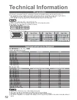
PC connection
A PC may be connected to this TV so that the PC screen is displayed and sound is heard from the TV.
•
PC signals that can be inputted: Horizontal scanning frequency 31 to 69 kHz; vertical scanning frequency
59 to 86 Hz (more than 1,024 signal lines could result in incorrect display of the image).
•
A PC adapter is not necessary for the DOS/V-compliant D-sub 15-pin connector.
Note
•
Some PC models cannot be connected to this TV.
•
When using PC, set the colour display quality of PC to the highest position.
•
For details of the applicable PC signals, see below.
•
Max. display resolution
Aspect
4:3
1,440 × 1,080 pixels
16:9
1,920 × 1,080 pixels
•
D-sub 15-pin connector signal
1
6
7
8
3
9
4
5
10
15 14 13 12 11
2
Pin No.
Signal Name
Pin No.
Signal Name
Pin No.
Signal Name
R
GND (Ground)
NC (not connected)
G
GND (Ground)
NC (not connected)
B
GND (Ground)
HD
NC (not connected)
NC (not connected)
VD
GND (Ground)
GND (Ground)
NC (not connected)

