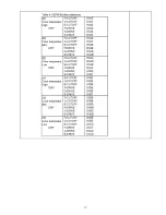
Table 1: R-CUT,G-CUT,B-CUT setting data
C o lo r te m p e ra tu r
R -CU T
G -C U T
B -C U T
H igh(C ool)
80
80
80
Mid
80
80
80
Low (W arm )
80
80
80
Table 2: W /B a d ju stm e n t values
Color temperature
X
У
High(Cool)
0.276
0 .280
Mid
0.288
0 .303
Low(Warm)
0.313
0.329
Table 3: E EP R O M d a ta a d d re sse s
SD
Color temperatur
High
R-CUTOFF
G-CUTOFF
B-CUTOFF
R-DRIVE
G-DRIVE
B-DRIVE
017C
017D
017E
017F
0180
0181
SD
R-CUTOFF
0182
Color temperatur
G-CUTOFF
0183
Mid
B-CUTOFF
0184
R-DRIVE
0185
G-DRIVE
0186
B-DRIVE
0187
SD
R-CUTOFF
0188
Color temperatur
G-CUTOFF
0189
Low
B-CUTOFF
018A
R-DRIVE
018B
G-DRIVE
018C
B-DRIVE
018D
HD
R-CUTOFF
018E
Color temperatur
G-CUTOFF
018F
High
B-CUTOFF
0190
R-DRIVE
0191
G-DRIVE
0192
B-DRIVE
0193
HD
R-CUTOFF
0194
Color temperatur
G-CUTOFF
0195
Mid
B-CUTOFF
0196
R-DRIVE
0197
G-DRIVE
0198
B-DRIVE
0199
HD
R-CUTOFF
019A
Color temperatur
G-CUTOFF
019B
Low
B-CUTOFF
019C
R-DRIVE
019D
G-DRIVE
019E
B-DRIVE
019F
30
Summary of Contents for Viera TC-P50C2
Page 19: ...6 4 No Picture Input only y v h a t s lnPut 0Г 1 У Signal 19 ...
Page 32: ...32 ...
Page 33: ...10 Block Diagram 10 1 Main Block Diagram A D IG ITAL SIG NAL PROCESSO R 33 ...
Page 34: ...10 2 Block 1 4 Diagram ...
Page 35: ...10 3 Block 2 4 Diagram A D IG ITAL SIG N AL PROCESSO R 35 ...
Page 36: ...10 4 Block 3 4 Diagram I p PO W ER SUPPLY 36 ...
Page 38: ...38 ...
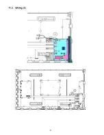
Page 40: ...11 3 Wiring 2 40 ...
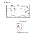
Page 41: ...11 4 Wiring 3 41 ...
Page 42: ...42 ...
Page 47: ...14 15 16 17 18 45 ...
Page 49: ...24 25 26 27 ...
Page 57: ...12 10 A Board 9 14 Schematic Diagram 52 ...
Page 59: ...12 12 A Board 11 14 Schematic Diagram A 91 92 93 94 95 96 97 98 99 TO 1 6 10 14 54 0 0 0 ...
Page 60: ...12 13 A Board 12 14 Schematic Diagram 100 1 101 1 102 1 103 1 104 1 105 1 106 1 107 1 108 55 ...
Page 63: ...12 16 C1 Board Schematic Diagram D A C1 B O A R D T X N C 11LNUU 58 ...
Page 64: ...1 I Н X I I H I I I 6 7 8 9 ...
Page 65: ...12 17 C2 Board Schematic Diagram A C D B E F i 2 3 4 8 9 5 59 ...
Page 67: ...12 19 SC Board 2 4 Schematic Diagram 10 11 12 13 14 15 16 17 18 61 ...
Page 70: ...12 22 SS Board 1 2 Schematic Diagram A C D A B E F 6 5 7 64 ...
Page 73: ...S BOARD FOIL SIDE TXN S1EQUUM S BOARD COMPONENT SIDE TXN S1EQUUM F I G I H ...
Page 74: ...Z9 9 SnnNI l V NXl aais nod aavoa v pjeog v Z ZV ...
Page 75: ...68 ...
Page 77: ...13 4 C2 Board 6 3 C2 BOARD COMPONENT SIDE TXNC21LNUU 70 ...
Page 78: ...13 5 SC Board 71 ...
Page 79: ...SC BOARD COMPONENT SIDE TXNSC1LNUU G 6 5 4 3 2 1 E F H 72 ...
Page 80: ...13 6 SS Board 6 5 4 SS BOARD FOIL SIDE TXNSS1LNUU ...
Page 81: ...1 I F I G I H 73 ...
Page 82: ...6 5 4 SS BOARD COMPONENT SIDE TXNSS1LNUU A В С D ...
Page 83: ...74 ...
Page 85: ...14 1 2 Exploded View 2 76 ...
Page 86: ...14 1 3 Accessories 77 ...


