background image

Getting started

Precautions

SQT0852

15

Additionally required accessories (commercially available)

Fall prevention cord  .....................................................................................................................  

2

Screw eyes (to attach the fall prevention cord) ............................................................................  

k

 2


Use commercially available screws that are capable of supporting over 26 k

g

.

Use a cord that is capable of supporting over 26 k

g

 (with a diameter of about 1.5 mm).

Lay the unit on a blanket or soft cloth for assembly.

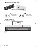
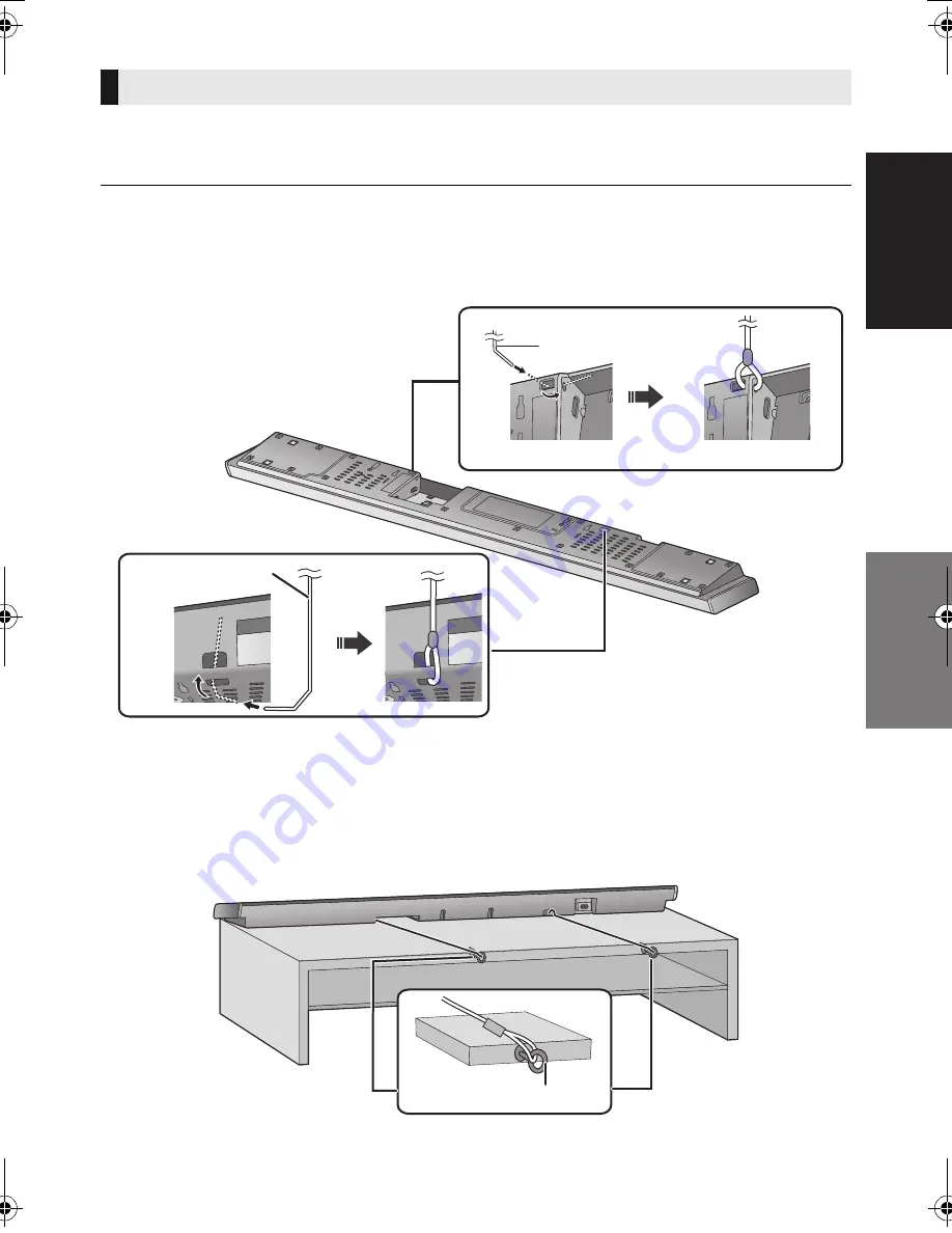
1 Attach the cord to the main unit.

A

Cord

§

§

 If the cord cannot be threaded through the holes, try bending the cord in 2 locations, 

about 5 mm apart from the tip, at an angle of 45

o

 (as


illustrated above).

2 Place the main unit in the desired position and attach each cord onto the rack or 

table.

Make sure that the slack of the cord is minimal.

Do not lean the main unit against the TV or wall.

B

Screw eye

Attach at a position capable of supporting over 26 k

g

.

Depending on the placement of the main unit, the screwing position of the screw eye may differ.

When placing the main unit in a rack or on a table

SC-HTB690-SQT0852.book  15 ページ  2015年1月30日 金曜日 午後2時2分

Summary of Contents for viera SC-HTB690

Page 1: ...or future use Model number suffix EB denotes UK model Included Installation Instructions The installation work should be done by a qualified installation specialist 13 to 18 Before commencing work carefully read these installation instructions and the operating instructions to ensure that installation is performed correctly Please keep these instructions You may need them when maintaining or movin...

Page 2: ...y out of reach of children to prevent swallowing Never put Button Type battery in mouth If swallowed call your doctor Unit Do not place sources of naked flames such as lighted candles on this unit This unit may receive radio interference caused by mobile telephones during use If such interference occurs please increase separation between this unit and the mobile telephone This unit is intended for...

Page 3: ...eplace the fuse The location of the fuse differ according to the type of AC mains plug figures A and B Confirm the AC mains plug fitted and follow the instructions below Illustrations may differ from actual AC mains plug 1 Open the fuse cover with a screwdriver 2 Replace the fuse and close or attach the fuse cover Figure A Figure B Fuse cover Figure A Figure B Fuse 10 ampere Fuse 10 ampere About d...

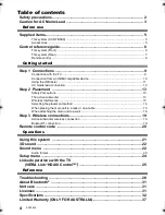
Page 4: ...t 13 Safety Precautions 13 The active subwoofer 13 Wireless interference 13 Selecting the placement method 14 When placing the main unit in a rack or on a table 15 When attaching the main unit to a wall 16 Step 3 Wireless connections 19 Active subwoofer wireless connection 19 Bluetooth connection 19 Remote control code 20 Operations Using this system 21 3D sound 22 Sound menu 22 Audio format 23 Se...

Page 5: ...m other equipment with this system This system SC HTB690 1 Main unit speaker SU HTB690 1 Active subwoofer SB HWA690 Accessories 1 Remote control with a battery N2QAYC000098 1 IR Blaster SFQ0014 2 Wall mount brackets RMQ2281A RMQ2281B 1 AC mains lead for the main unit For the United Kingdom and Ireland SFQ0017 For Continental Europe SFQ0015 For Australia and New Zealand SFQ0021 1 AC mains lead for ...

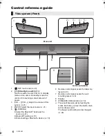
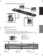
Page 6: ...put source 21 5 PAIRING Select the Bluetooth device as the source 21 Bluetooth pairing 19 Disconnecting a Bluetooth device 19 6 Remote control signal sensor for table top layout 8 7 Remote control signal sensor for wall mounting layout 8 8 Display 9 WIRELESS LINK indicator 19 These switches work just by touching the marks Each time you touch the switch there will be a beep sound The beep sound set...

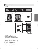
Page 7: ...ICAL DIGITAL AUDIO IN TV terminal 10 4 Ir SYSTEM terminal 11 5 AC IN terminal 12 6 Í I Active subwoofer on off button 19 1 USB port for service use only 2 The I D SET button is only used when the main unit is not paired with the active subwoofer 30 This system Rear 3 4 1 2 5 5 6 1 2 Main unit Active subwoofer ...

Page 8: ...t A Dispose of the insulation sheet responsibly after removing it To replace a button type battery Battery type CR2025 Lithium battery Set the button type battery with its i mark facing upward About remote control signal sensor The remote control signal sensor is located on the main unit Use the remote control within the correct operation range Distance Within approx 7 m directly in front Angle Ap...

Page 9: ...3D compatible Blu ray Disc player to a FULL HD 3D TV 4K 60p compatibility Compatible with 4K Ultra HD TV and Blu ray Disc player This system can pass through the 4K content of a 4K compatible equipment to a 4K Ultra HD TV When connecting to 4K compatible equipment and 4K Ultra HD TV use High Speed HDMI cables which support 18 Gbps bandwidth IR Infrared Blaster Do not use the IR Blaster if the TV s...

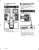
Page 10: ... system Preparation Connect the main unit to the TV 9 A HDMI cable B Not labelled HDMI ARC HDMI IN OPTICAL OUT TV Connection from an HDMI compatible device Refer to the operating instructions of the connected HDMI compatible device for the necessary setting to output the video and audio signals When connecting to 4K compatible equipment and 4K Ultra HD TV use High Speed HDMI cables which support 1...

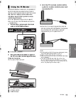
Page 11: ...ain unit B TV remote control signal sensor C Infrared emitter D Adhesive tape 3 Aim the TV s remote control at this system s remote control sensor and operate the TV When the TV receives signals from both its remote control and the IR Blaster their signals may interfere with each other making it impossible for you to operate the TV Using the IR Blaster For the location of the TV s remote control s...

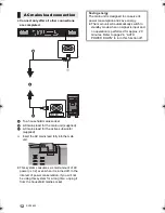
Page 12: ... AC power 32 even when it is turned off In the interest of power conservation if you will not be using this system for a long time unplug it from the household mains socket AC mains lead connection Saving energy The main unit is designed to conserve its power consumption and save energy The main unit will automatically switch to standby mode when no signal is input and no operation is performed fo...

Page 13: ...DEATH RESULTING FROM IMPROPER INSTALLATION OR INCORRECT HANDLING Be sure to install the main unit as indicated within this operating Instructions Attach using techniques suited to the structure and materials of the installation location Caution This system is to be used only as indicated in these instructions Failure to do so may lead to damage to the amplifier and or the speaker and may result in...

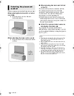
Page 14: ...V s remote control sensor is blocked by the main unit Try using the TV s remote control from a different angle If the problem persists you can use the supplied IR Blaster to relay the signal to the TV 11 Selecting the placement method Page 15 Page 16 Place the active subwoofer within a few meters of the main unit and in a horizontal position with the top panel facing upward Do not use the main uni...

Page 15: ...tach the cord to the main unit A Cord If the cord cannot be threaded through the holes try bending the cord in 2 locations about 5 mm apart from the tip at an angle of 45o as illustrated above 2 Place the main unit in the desired position and attach each cord onto the rack or table Make sure that the slack of the cord is minimal Do not lean the main unit against the TV or wall B Screw eye Attach a...

Page 16: ...safety measure Supplied accessories Additionally required accessories commercially available Screws for wall mounting k 2 Fall prevention cord k 2 Screw eyes to attach the fall prevention cord k 2 Use a cord that is capable of supporting over 26 kg with a diameter of about 1 5 mm Lay the unit on a blanket or soft cloth for assembly 1 Attach the cord to the main unit A Cord If the cord cannot be th...

Page 17: ...mm of space above of the main unit to allow enough space for fitting the main unit Position the main unit with at least 50 mm of free space to its right If not it may not be possible to access the touch keys Be sure to use a level to ensure that both mounting holes are level to each other Front view semi transparent image C At least 30 mm D 4 0 mm E 7 0 mm to 9 4 mm F Wall or pillar G 5 5 mm to 6 ...

Page 18: ...he screw s 5 Secure the cord to the wall Make sure that the slack of the cord is minimal A Screw eye B Cord DO DO NOT Move the speaker so that the screw is in this position In this position the speaker will likely fall if moved to the left or right ...

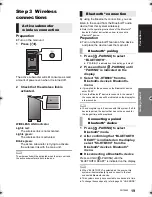
Page 19: ...NG is indicated on the display go to step 3 2 Press and hold PAIRING until PAIRING is indicated on the display 3 Select SC HTB690 from the Bluetooth device s Bluetooth menu If prompted for the passkey on the Bluetooth device enter 0000 Once the Bluetooth device is connected the name of the connected device will be indicated on the display for a few seconds You can register up to 8 devices with thi...

Page 20: ...cation of the NFC touch area differs depending on the device When a connection cannot be established even if your Bluetooth device has touched the NFC touch area of the main unit change the position of the device or main unit The condition may also improve if you download the dedicated app Panasonic Music Streaming and start it up 3 Start playback on the Bluetooth device If you touch another devic...

Page 21: ...he sound Press MUTE While muting MUTE is indicated on the display To cancel press the button again or adjust the volume Muting is cancelled if the main unit is turned off If there is sound coming out of the TV s speakers reduce the volume of the TV to its minimum There may be a difference in the maximum volume value of the TV and the unit When playing equipment connected to the HDMI AV IN terminal...

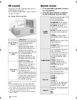
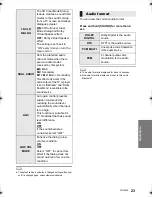
Page 22: ...om TV dramas are heard as if the sound is coming from the TV giving the feeling that the sound and the image are one Also the dialog will stand out from the other sounds during normal volume playback and when the volume is lowered for night time viewing e g Image of 3D sound field SOUND MODE Select the sound mode to suit the TV programme or connected equipment STANDARD Best suited for dramas and c...

Page 23: ...referred audio channel mode when there are two audio modes received by this system M1 Main M2 Secondary M1 M2 Main Secondary This effect only works if the audio output of the TV or player is set to Bitstream and Dolby Dual Mono is available in the sound source AGC Auto gain control prevents sudden loud sound by reducing the sound level automatically when the input is too high This function is suit...

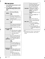
Page 24: ...Sets the volume limit to 50 when you turn on the main unit although the volume is set to above 50 before it is turned off ON OFF BLUETOOTH STANDBY This function allows you to connect a paired Bluetooth device when the main unit is in standby mode ON OFF The main unit will be turned on automatically when you connect a paired Bluetooth device If this function is set to ON the standby power consumpti...

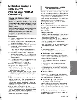
Page 25: ... Link menu The availability and function of the settings may vary depending on the TV Refer to the operating instructions for the TV for details Speaker control You can select whether audio output is from this system or the TV speakers by using the TV menu settings Home cinema This system is active When the main unit is in standby mode changing the TV speakers to this system in the VIERA Link menu...

Page 26: ...ed to standby mode AUTO POWER DOWN function is on The main unit will automatically switch to standby mode when no signal is input and no operation is performed for approx 20 minutes Refer to page 24 to turn this function off The main unit is turned off when the TV s speakers are selected in the speaker control This is a normal feature when using VIERA Link HDAVI Control 4 or later Please read the ...

Page 27: ...le the main unit and the TV are connected with the HDMI cable turn on the TV and then remove the main unit s AC mains lead and reconnect it again The first few seconds of audio cannot be heard when using the HDMI connection This may occur during DVD Video chapter playback Change the digital audio output setting on the connected device from Bitstream to PCM When operating an HDMI compatible device ...

Page 28: ...s system 32 Turn this system off and then on again If the main unit is connected to the TV with only an HDMI cable make sure that the TV s HDMI terminal is labelled HDMI ARC If not connect using the optical digital audio cable 9 10 If the main unit is connected to a Panasonic TV and turned on using the remote control or the touch key on the main unit sound might not be output from this system In t...

Page 29: ...t and then switch it on again Disconnect the HDMI cable F76 There is a problem with the power supply Disconnect the AC mains lead and consult the dealer U704 This system is receiving unsupported video format signal from the input source jChange the video resolution setting on the connected device Refer to the operating instructions for the device jIf there is no image connect the device directly t...

Page 30: ...ctive subwoofer off disconnect the AC mains lead and then reconnect it The active subwoofer and the main unit may not be paired correctly Try the following operation Wireless pairing 1 Turn on the main unit and active subwoofer 2 Press and hold I D SET on the rear of the active subwoofer for more than 3 sec The WIRELESS LINK indicator will blink in red 3 While pressing and holding INPUT on remote ...

Page 31: ...es etc Unit care Clean this system with a soft dry cloth When dirt is heavy wring a cloth moistened in water tightly to wipe the dirt and then wipe it with a dry cloth When cleaning the speakers use a fine cloth Do not use tissues or other materials towels etc that can fall apart Small grains may get stuck inside the speaker cover Never use alcohol paint thinner or benzine to clean this system Bef...

Page 32: ...igital DTS Digital SurroundTM IR Blaster Terminal Type 3 5 mm jack USB Port For service use only GENERAL Power consumption Main unit 40 W Active subwoofer 30 W In standby condition Main unit When BLUETOOTH STANDBY is OFF Approx 0 48 W When BLUETOOTH STANDBY is ON Approx 1 5 W Active subwoofer Power switch off Approx 0 48 W The wireless link is not activated Approx 1 0 W Power supply AC 220 V to 24...

Page 33: ...ull range 6 5 cm cone type k1 Bass reflex type Active subwoofer Woofer 16 cm cone type k1 Bass reflex type WIRELESS SECTION Frequency Range 2 40335 GHz to 2 47735 GHz No of channels 38 Bluetooth SECTION Bluetooth system specification Bluetooth Ver 2 1 EDR Wireless equipment classification Class 2 2 5 mW Supported profiles A2DP Frequency band 2 4 GHz band FH SS Operating distance approx 10 m Line o...

Page 34: ... Marketing Europe GmbH Panasonic Testing Centre Winsbergring 15 22525 Hamburg Njemačka Ovaj proizvod je namijenjen za opću potrošnju kategorija 3 Lietuviškai Atitikties deklaracija AD Bendrovė Panasonic Corporation patvirtina kad šis gaminys tenkina direktyvos 1999 5 EB esminius reikalavimus ir kitas taikytinas nuostatas Mūsų R TTE gaminių originalios atitikties deklaracijos kopiją klientai gali a...

Page 35: ...Marketing Europe GmbH Panasonic Testing Centre Winsbergring 15 22525 Hamburg Germania Acest produs a fost proiectat pentru clientela generală Categoria 3 Magyar Megfelelőségi Nyilatkozat DoC Ezennel a Panasonic Corporation kijelenti hogy a jelen termék kielégíti az 1999 5 EK Irányelv létfontosságú követelményeit és más vonatkozó rendelkezéseit A vásárlók letölthetik az R TTE termékek eredeti DoC m...

Page 36: ...aviser duker gardiner eller lignende Disposal of Old Equipment and Batteries Only for European Union and countries with recycling systems These symbols on the products packaging and or accompanying documents mean that used electrical and electronic products and batteries must not be mixed with general household waste For proper treatment recovery and recycling of old products and used batteries pl...

Page 37: ...tre Locator In addition to your rights under this warranty Panasonic products come with consumer guarantees that cannot be excluded under the Australian Consumer Law If there is a major failure with the product you can reject the product and elect to have a refund or to have the product replaced or if you wish you may elect to keep the goods and be compensated for the drop in value of the goods Yo...

Page 38: ...38 SQT0852 ...

Page 39: ...SQT0852 39 ...

Page 40: ...ing public holidays For further support on your product please visit our website www panasonic co uk Direct Sales at Panasonic UK Order accessory and consumable items for your product with ease and confidence by phoning our Customer Communications Centre Monday Friday 9 00 am 5 00 pm Excluding public holidays Or go on line through our Internet Accessory ordering application at www pas europe com M...

Reviews: