background image

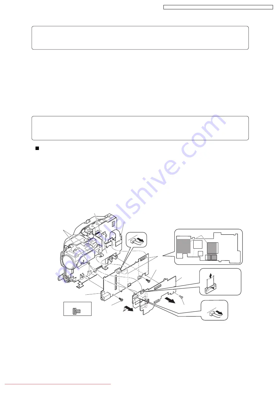
(14) AEL-H/AEL and MAN-H/MAN Circuit Boards

Note:

Before replacing the MAN-H/MAN circuit board, always perform “4-9-2 EEPROM data backup

and write”.

1) Disconnect the two flat cables.

2) Disconnect the DRF-H/DRF circuit board (c) from MAN-H/MAN circuit board (b).

3) Remove three screws [G].

4) Remove the AEL-H/AEL circuit board (a) that is assembled with MAN-H/MAN circuit board in

the direction of the arrow: It may be difficult to remove these circuit boards, since the heat sink

rubbers (e) on MAN-H/MAN circuit board may stick to the frame (d).

5) Remove the AEL-H/AEL circuit board from MAN-H/MAN circuit board in the direction of the

arrow.

Note:

Do not scratch the surface of IC2009 or IC2010: The surfaces of IC2009 or IC2010 are silicon

substrate (silicon wafer) that is semi-conducting. Scratching them could cause fault in operation.

Procedure and caution for reassembly

1) Be sure to paste the two heat sink rubbers (e) on the MAN-H/MAN circuit board: Neglecting to

paste the heat sink rubber could cause a fault.

2) Connect the MAN-H/MAN circuit board and AEL-H/AEL circuit board, and then attach them to

the frame. If the MAN-H/MAN and AEL-H/AEL circuit boards are attached to the frame

independently, a connection fault could result.

Fig. 5-3-17

(a) AEL-H/AEL circuit board
(b) MAN-H/MAN circuit board
(c) DRF-H/DRF circuit board
(d) Frame
(e) Heat sink rubbers

(1) Unloc

k

(2) Pull

3) [G]

4)

5)

2) (c)

e

e

1)

(1)

(2)

3) [G]

3) [G]

(d)

(b)

(a)

(b)

VDR-M70PP

VDR-M50PP

[G] M1.7x3 (Gold)

IC2006

IC4002

IC4106

IC2010

IC2009

IC2010

73

VDR-M70EG / VDR-M70EB / VDR-M70GC / VDR-M50EG / VDR-M50EB / VDR-M50GC

Downloaded From CamcorderManual.com Panasonic Manuals

Summary of Contents for VDR-M70EG

Page 1: ...of law VDR M70EG VDR M70EB VDR M70GC VDR M50EG VDR M50EB VDR M50GC M70 or TYPE M70 and M50 or TYPE M50 in this manual stands for the model shown below M70 or TYPE M70 VDR M70EG EB GC M50 or TYPE M50...

Page 2: ...AGNOSIS FUNCTION AND TROUBLESHOOTING 42 4 6 CHECKING VERSIONS OF FIRMWARE AND UPDATING 47 4 7 TROUBLE DIAGNOSIS 50 4 8 PROCEDURE FOR REMOVING DISC FROM FAULTY VDR M70 M50 57 4 9 SPECIAL FUNCTIONS 58 5...

Page 3: ...Do not use an isolation transformer for this check 2 Connect a 1 5 k 10 W resistor in parallel with a 0 15 F capacitor between each exposed metallic part on the set and a good earth ground as shown in...

Page 4: ...lder or unsolder ES devices 4 Use only an antistatic solder removal device Some solder removal devices not classified as antistatic ESD protected can generate electrical charge sufficient to damage ES...

Page 5: ...e capacitor on FRONT C B A before disassembling the Front C B A 2 Be careful of the high voltage circuit on Front C B A when servicing 1 4 1 REPLACEMENT PROCEDURE 5 VDR M70EG VDR M70EB VDR M70GC VDR M...

Page 6: ...sed from your local Panasonic Dealer If the fitted moulded plug is unsuitable for the socket outlet in your home then the fuse should be removed and the plug cut off and disposed of safety There is a...

Page 7: ...cement Component replacement Component replacement Component replacement Component replacement Component replacement Fig 2 1 1 1 The board names suffixed with H are for VDR M70 only 2 Film type board...

Page 8: ...ed 40 for photo 3 lx When Low Light mode is selected 0 33 inch color TFT approx 110 000 pixels 2 5 inch color TFT approx 120 000 pixels Electronic Type 1 60 1 4000 second video Still recording only 3...

Page 9: ...d DVD video recording DVD VR format 704 480 pixels JPEG of external input 640 480 pixels Movie Conforming to DVD video format Audio MPEG Audio layer 2 1 Still Conforming to JPEG VDR M70 1280 960 pixel...

Page 10: ...nput function is provided in the following models VDR M70GC VDR M50GC Specifications are subject to change without notice for the purpose of improvement Specifications of VSK0631 0631 A AC Adapter Cha...

Page 11: ...VDR M50 Optical 18 500 with digital zoom added 40 for photo 37 mm 3 lx When Low Light mode is selected 0 33 inch color TFT approx 110 000 pixels 2 5 inch color TFT approx 120 000 pixels VDR M70 Appro...

Page 12: ...rox 64 89 146 mm VSK0631 EG EB VSK0631 A GC Provided CGS DU14E 7 2V 1360mA Optional CGS DU14E 7 2V 1360mA VEQ3993 Pin 8 type Provided Software disc protect VDR M70 Video mode only VDR M50 Video and ph...

Page 13: ...d or edited on VDR M70 M50 can also be recorded edited and played back on other DVD video camera recorders except for those for which disc protect 1 has been set Discs recorded or edited on other DVD...

Page 14: ...2 5 NAME OF PARTS 14 VDR M70EG VDR M70EB VDR M70GC VDR M50EG VDR M50EB VDR M50GC Downloaded From CamcorderManual com Panasonic Manuals...

Page 15: ...15 VDR M70EG VDR M70EB VDR M70GC VDR M50EG VDR M50EB VDR M50GC Downloaded From CamcorderManual com Panasonic Manuals...

Page 16: ...16 VDR M70EG VDR M70EB VDR M70GC VDR M50EG VDR M50EB VDR M50GC Downloaded From CamcorderManual com Panasonic Manuals...

Page 17: ...17 VDR M70EG VDR M70EB VDR M70GC VDR M50EG VDR M50EB VDR M50GC Downloaded From CamcorderManual com Panasonic Manuals...

Page 18: ...D RW Video recording playback standard that applies to DVD RAM and DVD RW This allows versatile editing functions differing from the DVD Video Format Exchangeable image file format File format used fo...

Page 19: ...dustry Association of America RIAA and music industry companies to protect copyrights of musical compositions Formally named Secure Digital Memory Card This compact memory card 32 mm long 24 mm wide 2...

Page 20: ...ccessory shoe on VDR M50 doesn t 2 Lens unit The lens unit in VDR M50 includes the cushion crystal filter CCD image sensor and SEN circuit board which are discrete from the lens unit in VDR M70 VDR M5...

Page 21: ...gs 2 Take note of settings on received product referring to 4 2 System Resetting Resetting Camera Functions The notes will be necessary not only for resetting but for checking defects that occur under...

Page 22: ...steps operate the VDR M70 M50 while viewing the LCD monitor or viewfinder 3 Press the MENU button to display the camera function setup menu screen Make sure of the settings 4 Operate the joystick to...

Page 23: ...r Indoor1 Indoor2 On Off 240 40 Off On Off On Off With DVD RAM disc XTRA FINE STD With DVD R disc FINE STD FINE NORM ECO CAMERA LINE S LINE Frame Field On Off On Off PM5 00 Y M D 5 00PM M D Y 17 00 D...

Page 24: ...r the following steps operateVDR M70 M50 while viewing the LCD monitor or viewfinder 3 Set the quick mode switch to OFF 4 Press the MENU button to display the camera setting menu screen 5 Use the joys...

Page 25: ...batteries on hand Battery may be dead Replace with a new one The performance of battery will deteriorate if it is used for an extended period of time or frequently Is the ambient temperature is too lo...

Page 26: ...ck Has brightness of LCD screen been adjusted Stop recording and adjust the brightness Is VDR M70 M50 being used outdoors Use the viewfinder When using LCD monitor adjust angle so that LCD screen is n...

Page 27: ...or fingerprint adhere to disc or is disc scratched Clean the disc Was the image input from analog VCR VHS 8 mm and recorded The problem may be improved if a VCR equipped with TBC time base corrector...

Page 28: ...nd try again The DISC EJECT button is invalid while VDR M70 M50 is connected to PC Start Windows Explorer right click the drive icon corresponding to VDR M70 M50 and then click Eject Was DVD MovieAlbb...

Page 29: ...h images recorded on DVD RAM disc It cannot edit video DVD VR data stored on hard disk of PC To edit image data stored on hard disk copy the data to DVD RAM disc and then edit it Is a disc other than...

Page 30: ...AC adapter charger to the VDR M70 M50 and AC outlet set the power switch on VDR M70 M50 to POWER OFF and then leave them for at least 24 hours Is the cursor placed on scene to be deleted Even if desir...

Page 31: ...proper orientation Remove the round DVD holder make sure of the orientation and then reinsert it Is VDR M70 M50 turned on Connect the AC adapter charger or full charged battery and set the power switc...

Page 32: ...R disc The specifications state that no photo is recordable on DVD R disc Troubleshooting Replace with a charged battery or use the AC adapter charger to power VDR M70 M50 Stop trying to combine scen...

Page 33: ...se its terminals are dirty Also appears when data other than photos is recorded on card Appears when the recording capacity of card has reached the limit during recording Appears when a card whose rem...

Page 34: ...Choose YES and designate partial repair automatic repair of video file Choosing NO will display a message for verifying initialization 3 Do not execute repair but set the power switch to POWER OFF wi...

Page 35: ...corded data Also appears when reading or writing from to recorded file cannot be performed because the disc is dirty Appears when the disc could not be finalized because it was dirty Appears if accide...

Page 36: ...rite protect for program units The DVD Forum defines two types of software protect for DVD RAM disc disc units and program units Appears if the number of scenes on play list exceeds the upper limit 99...

Page 37: ...f scene was selected to divide the scene The specifications state that dividing a scene at its end is not possible Appears if the self diagnosis function of VDR M70 M50 has detected a serious problem...

Page 38: ...le Repair data now appeared Appears if the self diagnosis function in VDR M70 M50 detects a serious problem during recording or when the same trouble occurs three times consecutively during recording...

Page 39: ...deleted the play list will also be deleted Appears if an attempt is made to create a new play list or edit play list after the number of registered play lists has reached the upper limit 99 that is de...

Page 40: ...C system and does not comply with the PAL system Appears when the first image of scene was selected to divide the scene The specifications state that dividing a scene at its top is not possible Appear...

Page 41: ...en an SD memory card whose erasure prevention switch was locked is loaded Terminate the Disc Navigation function set the power switch to POWER OFF with the disc loaded remove the battery and then conn...

Page 42: ...ower was turned on following the procedure below Procedure when message shown in Fig 4 5 1 appears Set the power switch to POWER OFF reconnect the AC adapter charger or battery and then set the power...

Page 43: ...aracters will directly appear and similar messages will appear if a problem from the same cause occurs three times consecutively during operation If messages for serious problems appear perform troubl...

Page 44: ...t this the error code will always be displayed 2 Details of error code display 1 Error codes of 2 problems are displayed one above the other The error code of the latest problem appears in the upper r...

Page 45: ...place the disc without regard as to whether it is dirty scratched or distorted Replace the disc 1 Check the ambient temperature 2 Set the power switch to POWER OFF remove the disc and check whether or...

Page 46: ...Take care not to subject VDR M70 M50 to impact or vibrations at this time 2 Set the power switch to POWER OFF remove the disc and check whether or not it is dirty scratched or distorted If it is dirty...

Page 47: ...6 1 Checking firmware versions 1 Purpose When checking whether updating firmware is needed or not use the following procedure to view the information display or version display screen see Fig 4 6 1 an...

Page 48: ...numbers or alphabets Detail Model DVR M70 PAL System Ver x xx Date xxxx xx xx xx xx xx Cam Ver x xx Drive Main xxxx xx xx REV Drive Core xxxx xx xx REV RETURN Version Model VDR M70 PAL System Ver x xx...

Page 49: ...the AC adapter charger to power the VDR M70 M50 A battery cannot be used because it may interrupt power of VDR M70 M50 during work 3 Insert the disc card for updating firmware 4 Set the power switch t...

Page 50: ...70 M50 Set to the appropriate service position referring to Disassembly reassembly to enable service position If only dashes are entered in the service position column trouble diagnosis is possible wi...

Page 51: ...n approx 15 V DC C15V be confirmed Can approx 3 V DC B U3V be confirmed Even if manual focus is set and buttons are operated focus is not correct and when power is turned on again abnormal sound is he...

Page 52: ...approx 5 V DC INV5V be confirmed Can video signal EVF G be confirmed Can sensor drive pulses V1 4 H1 H2 RG be confirmed Can video signal CCD OUT be confirmed Does image appear on LCD monitor or in EV...

Page 53: ...nfirmed Can audio signal AUD L AUD R be confirmed Can audio signal MIC_INL MIC_INR be confirmed Can audio signal MIC_INL MIC_INR be confirmed Can audio signal EXTMIC_LCH EXTMIC_RCH be confirmed Yes Re...

Page 54: ...DISC COVER 21PIN 0 3 ZZ FFC 5 VFK1575C2325 PG1301 AEL LENS UNIT 23PIN 0 3 ZZ FFC 6 VFK1716 PG7008 AEL PG3401 LCD 25PIN 0 3 ZZ FFC 7 VFK1480 PG7004 AEL PG8012 L CASE 6PIN 0 5 FFC 8 VFK1282 PG0153 SHE E...

Page 55: ...55 VDR M70EG VDR M70EB VDR M70GC VDR M50EG VDR M50EB VDR M50GC Downloaded From CamcorderManual com Panasonic Manuals...

Page 56: ...0510 TL0513 TL0522 TL0515 TL0512 TL0517 TL2090 TL2085 TL2086 TL2082 TL2089 TL2091 TL2084 TL2095 TL0520 GND TL0521 GND TL0518 TL1547 TL1543 TL0511 TL0504 TL1535 TL1534 TL6006 TL6009 TL6010 MAN H MAN P...

Page 57: ...to remove disc If the disc cannot be ejected after performing 4 8 1 Item to be checked remove it using the procedure in this section Information Numbers in diagrams are step numbers of setting proced...

Page 58: ...e 2 Make sure that the DVD RAM disc to be formatted is free from dirt or scratch If the disc is dirty clean it if the disc is scratched replace it Any dirt or scratch on disc could disable normal form...

Page 59: ...e figure 2 Copy the adjustment program to HDD of PC Refer to 6 1 5 Copy or Deleting Adjustment Program for copying 3 Start the adjustment program in order to display the adjustment menu screen on PC d...

Page 60: ...BLK RED DC WER SUPPL 5V 1A GND PIN 16 SD PIN 20 RS 232C CABLE PC POWER CABLE To AC OUTLET DC POWER CORD REMO THE ADJUSTMENT VER SKYLARK CONNECTION JIG DSP R JIG VFK0631 PO Y VE CO 60 VDR M70EG VDR M70...

Page 61: ...confirmed using the PROGRESS STATUS dialog 7 When backup is complete the BACKUP FINISHED dialog will appear Click the OK button in dialog to restore the DATA INITIALIZE MENU screen 8 Then click the R...

Page 62: ...ialog 7 When writing is complete the INITIALIZATION FINISHED dialog will appear Click the OK button in dialog to restore the DATA INITIALIZE MENU screen 8 Click the RETURN button on DATA INITIALIZE ME...

Page 63: ...ard slot cover 5 2 ORDER OF DISASSEMBLY Refer to Disassembly Flowchart in Fig 5 2 1 for the order of removing components When reassembling components use the reverse order to removal unless otherwise...

Page 64: ...Side case L LCD Unit SWL2 circuit board Side case L Fulcrum cover U Fulcrum cover B Fulcrum unit 5 3 19 5 3 5 Jack cover FRT H FRT circuit board Microphone Microphone cover 5 3 6 Front case SHE circui...

Page 65: ...ment cover a and remove the adjustment cover in the direction of the arrow being very careful not to scratch the adjustment cover or side case L c with screwdriver 2 Hood Filter Piece and Lens Cover 1...

Page 66: ...d or fold it 5 Disconnect the flat cable between L and R blocks Disconnect the flat cable between L and R blocks Do not forcibly pull out the flat cable from connectors at this time 6 Remove the L blo...

Page 67: ...a Jack cover b Front block Fig 5 3 6 6 FRT H FRT circuit board Microphone and Microphone Cover FRT H FRT circuit board a 1 Disconnect the flat cable from microphone 2 Remove one screw D and then remo...

Page 68: ...isconnect the one flat cable 5 Remove two screws D and then remove the SWL2 circuit board c Note Take great care when handling the LCD unit The LCD unit has an LCD panel that is a precision component...

Page 69: ...ach at this time Take care not to lose it MR Circuit Board b 5 Disconnect the MR circuit board from the LCD circuit board g 6 Remove the MR circuit board in the direction of the arrow The MR circuit b...

Page 70: ...ned disc cover could damage the switch inside the disc cover 2 Pass the flat cable extending from the disc cover through the gap between the frame and side case R and then connect it to the MAN H MAN...

Page 71: ...case R g 5 Remove one screw F and one screw A 6 Disconnect the three flat cables and then remove the rear cover along with the EVF unit 7 Remove one screw A and then remove the EVF unit Hand Strap e...

Page 72: ...Fig 5 3 14 12 SHE Circuit Board in VDR M50 1 Disconnect the SHE circuit board a from AEL circuit board b 2 Disconnect the GYR circuit board c from SHE circuit board 3 Remove one screw G and then remo...

Page 73: ...f IC2009 or IC2010 are silicon substrate silicon wafer that is semi conducting Scratching them could cause fault in operation Procedure and caution for reassembly 1 Be sure to paste the two heat sink...

Page 74: ...era block contains the lens unit which is a precision component Subjecting the lens unit to any impact could result in a fault Fig 5 3 18 a Camera block b Frame c hook of camera frame d square hole in...

Page 75: ...he drive block The drive block contains the disc drive unit which is a precision component Do not subject the disc drive unit to any impact Doing so could cause a fault Fig 5 3 21 Bottom side a Drive...

Page 76: ...sc drive unit Lock Unit d and Frame e 5 Remove one screw H and then remove the lock unit Note The disc drive unit is a precision component Take great care when handling it Do not subject the disc driv...

Page 77: ...and then remove the LCD circuit board Be careful not to deform LCD frame c at this time a LCD case B b LCD circuit board c LCD frame Fig 5 3 24 LCD Case B and LCD Circuit Board Fig 5 3 25 Assembling p...

Page 78: ...H circuit board Note 1 The lens unit crystal filter and CCD image sensor are precision components Take great care when handling them Adherence of dust foreign object fingerprint etc to them scratches...

Page 79: ...GYR circuit board Lens Frame b and Lens Unit c 2 Remove two screws D and then remove the lens frame Caution 1 The lens unit is a precision component Take great care when handling it Do not allow any...

Page 80: ...eference data is usually created once for each model because it is recorded on hard disk drive HDD of PC with the adjustment program However creating reference data again is necessary in the following...

Page 81: ...pe Generally available AV S input output or output cable Accessory EW12522 AC adapter charger Accessory 2 Power cable for AC adapter charger Accessory 2 DC power cord 1 The adjustment program used on...

Page 82: ...light box VFK1164TDVLB 3 Color monitor color TV with AV input jacks 4 DC power supply for DSP R jig 5 V 1 A 5 DC power supply for Light box 12 V 2 A 6 1 3 Connections when Creating Reference Data Con...

Page 83: ...t the lead wires from jig face up VFK0631 WHT RD PIN 18 YEL BLK BLK RED RS 232C CABLE DSP R JIG POWER CABLE To OUTLET DC Power CORD DC POWER SUPPL 5V 1A GND PIN 16 SD PIN 20 TRIPOD YEL To VIDEO IN COL...

Page 84: ...oystick to choose ENTER and then press the center of joystick Reset will be executed 7 Press the MENU button to restore the normal display Information The following table shows the menu status after t...

Page 85: ...ng Reference Data Creation Program Make sure that the connections are correct the power switch on DVD video camera recorder is set to VIDEO and the DC power supply for DSP R jig is turned on The refer...

Page 86: ...R interface jig Clicking the OK button will finish the program After solving the problem restart the program When the communication port error dialog appears There was a mistake in selecting communic...

Page 87: ...reference data creating program does not work perform the following procedure 1 Set the power switch of reference data creating device to OFF 2 Turn off the DC power supply of DSP R interface jig 3 Si...

Page 88: ...e C12 light balancing filter from the lens of DVD video camera recorder and then click the OK button in REMOVE THE FILTER dialog After that the ATTACH THE FILTER dialog and REMOVE THE FILTER dialog ma...

Page 89: ...N button on the SETUP MENU screen with an unfinished item the EXECUTE OTHER ITEMS dialog will appear Click the OK button in EXECUTE OTHER ITEMS dialog and then execute the unfinished items SETUP MENU...

Page 90: ...ch you performed adjustment Yes Yes No No Yes No Create the reference data referring to section 6 1 It is not necessary to create the reference data Does the map04w folder exist on HDD of PC with whic...

Page 91: ...ustment cover removed see Fig 6 2 4 Do not attempt to perform any adjustment with the DVD video camera recorder disassembled Doing so is very dangerous because the DVD video camera recorder incorporat...

Page 92: ...18 YEL BLK BLK RED PC VFK0631 GND PIN 16 SD PIN 20 LCD HDD PIN FREQUENCY COUNTER VECTOR SCOPE OSCILLOSCOPE Nothing VECTOR SCOPE TRIPOD DC POWER SUPPL 5V 1A SKYLARK CONNECTION JIG RS 232C CABLE POWER C...

Page 93: ...eference data 2 Set the power switch to VIDEO and quick mode switch to OFF After that operate the DVD video camera recorder while watching the LCD monitor screen 3 Press the MENU button to display the...

Page 94: ...l of test equipment for details 1 Oscilloscope a Probe 10 1 b TIME DIV 10 or 20 s except where some other designation is given c VOLTS DIV Change depending on the measurement object d TRIGGER SOURCE C...

Page 95: ...n and then proceed with the MODEL SELECT screen Note If the dialogs on right appear perform the following troubleshooting When the power or connection error dialog appears A connection is incorrect or...

Page 96: ...n Information If the PC does not accept any operation during work or the reference data creating program does not work perform the following procedure 1 Set the power switch of reference data creating...

Page 97: ...T MENU PLL EXECUTE RETURN CONNECTION LCD ADJUSTMENT MENU CONTRAST BRIGHT WHITE BALANCE Data Initialize Initial Data Write EXECUTE RETURN CONNECTION FILE MENU Original Data Backup Backup Data Write AUT...

Page 98: ...9 2 EEPROM data backup and write before replacing the MAN H MAN circuit board 2 EEPROM data backup disabled refers to when the backup of EEPROM data from the MAN H MAN circuit board to be replaced co...

Page 99: ...LCD contrast 1 LCD bright LCD contrast 2 Item Initial Data Write Video Level Burst Level Sampling Pulse Autofocus Auto Iris Control Matrix Chroma Gain Spot Noise LCD PLL LCD Contrast 1 4 LCD Bright 4...

Page 100: ...a Write Video Level Burst Level Sampling Pulse Autofocus Auto Iris Control Matrix Chroma Gain Spot Noise LCD PLL LCD Contrast 1 LCD Bright LCD Contrast 2 LCD White Balance EVF BL DET Check EVF PLL EVF...

Page 101: ...itial Data Write on the DATA INITIALIZE MENU screen 4 Click the EXECUTE button on DATA INITIALIZE MENU screen to start writing of initial data The progress status can be confirmed using the PROGRESS S...

Page 102: ...U screen to the status before the adjustment was performed 5 When save is complete the ADJUSTMENT FINISHED dialog will appear Click the OK button in dialog to restore the ADJUST MENU screen ADJUST MEN...

Page 103: ...MENU screen to the status before the adjustment was performed 5 When save is complete the ADJUSTMENT FINISHED dialog will appear Click the OK button in dialog to restore the ADJUST MENU screen ADJUST...

Page 104: ...rting within 90 seconds after turning it on Unstable circuit operation will cause improper adjustment Preparation Cap the lens of DVD video camera recorder Procedure 1 Choose SAMPLING PULSE on the ADJ...

Page 105: ...then execute readjustment If the AF adjustment error dialog still appears even after troubleshooting the connection of lens unit may be incorrect or the unit may be faulty ADJUST MENU screen ADJUSTMEN...

Page 106: ...ustment If the IRIS ADJUSTMENT ERROR dialog still appears after the corrective action the lens unit may be faulty a Perform adjustment in a place where no surrounding light will affect the adjustment...

Page 107: ...TER dialog After that the ATTACH THE FILTER dialog and REMOVE THE FILTER dialog may occasionally appear Reattach the C12 light balancing filter and remove it each time 5 When adjustment is complete th...

Page 108: ...y light 3 Press the STOP button on DVD video camera recorder 4 Insert the color bar chart into light box and point the DVD video camera recorder at the chart so that it fills the screen MANUAL ADJUSTM...

Page 109: ...ick the SAVE button Note that clicking the RETURN button will restore the ADJUST MENU screen to the status before the adjustment was performed 10 When save is complete the ADJUSTMENT FINISHED dialog w...

Page 110: ...on the ADJUST MENU screen 2 Click the EXECUTE button on ADJUST MENU screen to start adjustment When SPOT NOISE starts the DVD video camera recorder will automatically turn on again 3 When adjustment...

Page 111: ...VD video camera recorder has shifted to the test mode the LCD screen will be black and white see Fig 6 4 7 and the LCD ADJUSTMENT MENU screen will appear on the PC monitor screen ADJUST MENU screen MA...

Page 112: ...ote that clicking the RETURN button will restore the LCD ADJUSTMENT MENU screen to the status before the adjustment was performed 5 When save is complete the ADJUSTMENT FINISHED dialog will appear Cli...

Page 113: ...ick the SAVE button Note that clicking the RETURN button will restore the LCD ADJUSTMENT MENU screen to the status before the adjustment was performed 5 When save is complete the ADJUSTMENT FINISHED d...

Page 114: ...e be sure to click the SAVE button Note that clicking the RETURN button will restore the LCD ADJUSTMENT MENU screen to the status before the adjustment was performed 5 When save is complete the ADJUST...

Page 115: ...plete be sure to click the SAVE button Note that clicking the RETURN button will restore the LCD ADJUSTMENT MENU screen to the status before the adjustment was performed 5 When save is complete the AD...

Page 116: ...tton and then proceed with the SUB BRIGHT RED ADJUSTMENT screen Note that clicking the RETURN button will restore the LCD ADJUSTMENT MENU screen to the status before the adjustment was performed 5 Use...

Page 117: ...dialog will appear Click the OK button in dialog to restore the LCD ADJUSTMENT MENU screen 13 Click the RETURN button in LCD ADJUSTMENT MENU to restore the ADJUST MENU screen SUB BRIGHT BLUE ADJUSTME...

Page 118: ...When the DVD video camera recorder has shifted to the test mode the viewfinder screen will be black and white see Fig 6 4 12 and the EVF ADJUSTMENT MENU will appear on the PC monitor screen ADJUST ME...

Page 119: ...creen 3 Click the UP or DOWN button to flatten the waveform Click the button at intervals of approx 2 seconds while observing the movement of waveform 4 After step 3 is complete be sure to click the S...

Page 120: ...king the RETURN button will restore the EVF ADJUSTMENT MENU screen to the status before the adjustment was performed 5 When save is complete the ADJUSTMENT FINISHED dialog will appear Click the OK but...

Page 121: ...ing the RETURN button will restore the EVF ADJUSTMENT MENU screen to the status before the adjustment was performed 5 When save is complete the ADJUSTMENT FINISHED dialog will appear Click the OK butt...

Page 122: ...sure to click the NEXT button and then proceed with the SUB BRIGHT RED ADJUSTMENT screen Note that clicking the RETURN button will restore the EVF ADJUSTMENT MENU screen to the status before the adju...

Page 123: ...when the check value is 5 V or Low button when it is 0 V 13 When BL DET is complete the ADJUSTMENT FINISHED dialog will appear Click the OK button in dialog to restore the EVF ADJUSTMENT MENU screen 1...

Page 124: ...124 VDR M70EG VDR M70EB VDR M70GC VDR M50EG VDR M50EB VDR M50GC Downloaded From CamcorderManual com Panasonic Manuals...

Page 125: ...6PIN 22PIN 22PIN PG1801 PG7003 PG7008 PG3401 PG3402 PG3403 PG7001 PG2001 PG1501 PG9404 PG2301 PG9103 PG9701 PG9702 PG9301 PG9401 PG9404 PG9403 PG2302 PG2002 PG5001 CN8101 J6002 J6001 PG1502 PG0501 PG1...

Page 126: ...PG0154 PG0153 PG1401 CN7004 CN8012 PG7002 PG1302 PG1802 22PIN FRT LCD GYR SHE SAF MAN USB DRF DRV R AEL MR MOD HDM MICROPHONE LENS UNIT LCD PANEL LOCK UNIT DISC DRIVE UNIT SLID MOTOR SPINDLE MOTOR EX...

Page 127: ...YRO H_GYRO M70 To SHE H PG0154 M50 To SHE PG0154 5H XP4501 CODE PART NAME ONE VOLTAGE PB OR REC MODE FRT H FRT 64 MO 1ZS LE LE 1ZS 64 MO 2SC5383T11 2SD2345 S DTC114TYE MA132WA To BTB AEL H AEL PG7003...

Page 128: ...6E 8E 1E 2F 3F 4F 5F 6F 7F 8F 1F 4 3 2 1 A B C D E F A B C D E F 8 7 6 5 4 3 2 1 8 7 6 5 S 5 DRF H DRF DRF H DRF To MAN PG2002 To DISC DRIVE UNIT DRV R PG9701 7E VDR M70EG EB GC VDR M50EG EBGC DRF H...

Page 129: ...2 4 0 1 4 1 4 1 4 1 4 1 4 1 4 1 4 3 1 3 1 0 3 1 3 1 3 1 3 1 0 0 1 4 0 5 2 4 1 0 1 6 1 6 0 5 0 5 2 4 1 0 1 4 0 5 PB 1 4 REC PB REC 0 0 3 1 0 3 1 0 3 1 PB REC 0 PB REC 0 4 3 1 0 4 8 1 0 2 9 1 6 1 6 1 6...

Page 130: ...S 10 SAF H SAF S 11 MR USB H USB FLC181Z16SMMZ PC TERMINAL To MAN H MAN PG5001 SAF H SAF To SWL2 PG8012 To BTB AEL H AEL PG7004 0 3 2 3 2 0 3 2 3 2 REVERSE SW OPEN CLOSE SW REVERSE MR To LCD PG3403 ON...

Page 131: ...2 4 0 1 4 1 4 1 4 1 4 1 4 1 4 1 4 3 1 3 1 0 3 1 3 1 3 1 3 1 0 0 1 4 0 5 2 4 1 0 1 6 1 6 0 5 0 5 2 4 1 0 1 4 0 5 PB 1 4 REC PB REC 0 0 3 1 0 3 1 0 3 1 PB REC 0 PB REC 0 4 3 1 0 4 8 1 0 2 9 1 6 1 6 1 6...

Page 132: ...R1350 M70 0 M50 180 M50 M50 M70 FOCUS ZOOM IRIS DRIVE 2A 7A 8A 9A 10A 18A 19A 5A 3A 17A 16A 4A 1A 6A 11A 20A 21A 22A 15A 14A 12A 13A BTB 1A 22A CODE PART NAME AE BQ LF N5 2SB1424R 2SC4617 2SC5383 T11...

Page 133: ...32C 33C 34C 36C 37C 38C 39C 40C 41C 42C 11C 5C 6C 7C 8C 10C 9C 12C 13C 14C 15C 16C 35C 17C 18C 1C 2C 3C 43C 4C 10B 11B 12B 13B 14B 15B 16B 17B 18B 19B EVF 1B 9B EVF 10B 19B BM10345R 336 N5 M70 EVF 20...

Page 134: ...R1350 M70 0 M50 180 M50 M50 M70 FOCUS ZOOM IRIS DRIVE 2A 7A 8A 9A 10A 18A 19A 5A 3A 17A 16A 4A 1A 6A 11A 20A 21A 22A 15A 14A 12A 13A BTB 1A 22A CODE PART NAME AE BQ LF N5 2SB1424R 2SC4617 2SC5383 T11...

Page 135: ...2 4 0 1 4 1 4 1 4 1 4 1 4 1 4 1 4 3 1 3 1 0 3 1 3 1 3 1 3 1 0 0 1 4 0 5 2 4 1 0 1 6 1 6 0 5 0 5 2 4 1 0 1 4 0 5 PB 1 4 REC PB REC 0 0 3 1 0 3 1 0 3 1 PB REC 0 PB REC 0 4 3 1 0 4 8 1 0 2 9 1 6 1 6 1 6...

Page 136: ...1 4 8 8 8 8 0 3 1 0 3 0 0 3 1 0 3 1 0 3 1 0 3 1 0 3 1 0 3 1 0 3 1 0 3 0 1 5 5 0 0 3 0 0 3 0 0 3 0 6 5 0 8 6 4 0 8 21B 20B 33B 23B 28B 27B 26B 25B 24B 32B 22B 30B 31B 29B EVF AEL H AEL N5 EVF DRIVER B...

Page 137: ...1 S 18 SWL2 SWL2 To SWL3 H SWL3 PG8017 To SIDE CASE L To SAF H SAF CN8012 CENTER L UP LOW R JOYSTICK STOP EXIT MENU SELECT DISC NAVIGATION VDR M70EG EB GC VDR M50EG EBGC SWL2 SCHEMATIC DIAGRAM VDR M70...

Page 138: ...IN 62 TEST2 61 TEST1 60 HDIN 59 VDIN 58 VSEP IC 57 SYNC IN 56 RESET 55 BIN 54 GIN 53 RIN 52 VREG REG CLAMP CNTRST CNTRST CONT SIG C BLKL1 RMTL1 R CONT B CONT BRT COM BRT B BRT R BRT S H BRIGHT SUB BRI...

Page 139: ...R SIDE B PATTERN No JD1175 3 GYR H SIDE A PG1401 GYR H SIDE B PATTERN No JD1176 5 VDR M70EG EB GC VDR M50EG EBGC GYR H GYR CIRCUIT BOARD DIAGRAM VDR M70EG VDR M70EB VDR M70GC VDR M50EG VDR M50EB VDR M...

Page 140: ...N No JD1176 5 PD1801 FRT SIDE A FRT SIDE B PATTERN No JD1175 3 PD1801 VDR M70EG EB GC VDR M50EG EBGC FRT H FRT CIRCUIT BOARD DIAGRAM VDR M70EG VDR M70EB VDR M70GC VDR M50EG VDR M50EB VDR M50GC 140 Dow...

Page 141: ...SIDE A 36 DRF H SIDE B PATTERN No JD1176 4 36 SHE SIDE A 1 20 40 21 SHE SIDE B PATTERN No JD1175 3 BA1801 VDR M70EG EB GC VDR M50EG EBGC DRF H DRF SHE CIRCUIT BOARD DIAGRAM VDR M70EG VDR M70EB VDR M7...

Page 142: ...TERN No JD1176 5 BA1801 C0153 SWL2 SIDE B PATTERN No JA2255 1 SWL2 SIDE A VDR M70EG EB GC VDR M50EG EBGC SHE H SWL2 CIRCUIT BOARD DIAGRAM VDR M70EG VDR M70EB VDR M70GC VDR M50EG VDR M50EB VDR M50GC 14...

Page 143: ...6 4 USB SIDE A 1 5 CN8101 USB SIDE B PATTERN No JD1175 3 MR PATTERN No JA1183 2 CN3401 VDR M70EG EB GC VDR M50EG EBGC USB H USB MR CIRCUIT BOARD DIAGRAM VDR M70EG VDR M70EB VDR M70GC VDR M50EG VDR M50...

Page 144: ...A 2A A A A A A 2A 2A C 1C C B 1B B 1B B B 1B B B 1A LCD SIDE B PATTERN No JA2244 4 A B C A B C 1 2 3 4 1 2 3 4 1C 1C 1 1C 1B 1 1B B 1B B B 1B B B 1 1 1 1B B 1 1 1A 2C 2C 2C 2C C C 2B B B B B B B B B B...

Page 145: ...H SIDE A CN7004 CN8012 SAF H SIDE B PATTERN No JD1176 5 SAF SIDE A CN7004 CN8012 SAF SIDE B PATTERN No JD1175 3 VDR M70EG EB GC VDR M50EG EBGC SEN H SAF H SAF CIRCUIT BOARD DIAGRAM VDR M70EG VDR M70EB...

Page 146: ...vided 180k 8 2k 27k 27k 39k 10k 5 6k 180 120 Not Pro vided Not Pro vided 1 120 61 60 R7031 TL7041 TL6102 TL6101 TL3715 TL7028 TL7030 AEL H AEL SIDE B PATTERN No JA2237 4 TL3701 GND A B C D E F G H A...

Page 147: ...D DIAGRAM IC2008 PG2001 LINE INPUT FUNCTION Provided Provided Not Provided Not Provided Provided Not Provided 16PIN 14PIN M70 EG EB M50 EG EB M70 GC M50 GC Note Voltage values are in REC status Model...

Page 148: ...s in which laser light is emitted from the pickup DRV R SIDE B PATTERN No JA2238 3 MOD SIDE A MOD SIDE B PATTERN No JA2238 3 VDR M70EG EB GC VDR M50EG EBGC DRV R MOD CIRCUIT BOARD DIAGRAM Information...

Page 149: ...MAN DRV R MOD and HDM Circuit Boards If a fault is located on the MAN H MAN circuit board the entire circuit board must be replaced for servicing If there is a fault in the DRV R MOD or HDM circuit bo...

Page 150: ..._OUT TL1536 SP_OUT 15 PG1501 42 PG7001 42 44 44 35 31 38 39 50 46 53 EVF DRIVER IC3701 21 23 21 23 PG7009 PG0151 LCD PANEL 53 55 40 43 45 TL3715 EVF G 4 37 38 4 37 38 PG0153 6 8 6 8 29 31 39 77 87 101...

Page 151: ...ual com Panasonic Manuals 25 26 PG9701 30 33 38 41 IC8501 30 IC9302 1 3 14 16 17 32 IC9304 15 16 IC9305 8 IC9306 8 IC9602 IC9603 6 8 IC9605 5 IC9610 8 PG9301 3 4 7 22 23 IC9301 11 12 41 PG9702 5 6 25...

Page 152: ...3 4 22 23 Q3451 BACK LIGHT SW IC7001 8 82 83 102 119 24 97 82 83 PG7009 10 30 30 3 20 PG0151 10 3 20 PG0154 1 8 IC1403 GYRO DET CN1401 1 3 IC1401 V_MOVE 3 IC1402 H_MOVE 3 IC1801 REMOTE CONTROL RECEIV...

Page 153: ...ual com Panasonic Manuals 25 26 PG9701 30 33 38 41 IC8501 30 IC9302 1 3 14 16 17 32 IC9304 15 16 IC9305 8 IC9306 8 IC9602 IC9603 6 8 IC9605 5 IC9610 8 PG9301 3 4 7 22 23 IC9301 11 12 41 PG9702 5 6 25...

Page 154: ...VDR M70EG VDR M70EB VDR M70GC VDR M50EG VDR M50EB VDR M50GC 154 Downloaded From CamcorderManual com Panasonic Manuals...

Page 155: ...8 EXPLODED VIEWS 8 1 MAIN SECTION 155 VDR M70EG VDR M70EB VDR M70GC VDR M50EG VDR M50EB VDR M50GC Downloaded From CamcorderManual com Panasonic Manuals...

Page 156: ...156 VDR M70EG VDR M70EB VDR M70GC VDR M50EG VDR M50EB VDR M50GC Downloaded From CamcorderManual com Panasonic Manuals...

Page 157: ...8 2 LCD BLOCK SECTION 157 VDR M70EG VDR M70EB VDR M70GC VDR M50EG VDR M50EB VDR M50GC Downloaded From CamcorderManual com Panasonic Manuals...

Page 158: ...8 3 CAMERA LENS SECTION 8 3 1 For VDR M70 8 3 2 For VDR M50 158 VDR M70EG VDR M70EB VDR M70GC VDR M50EG VDR M50EB VDR M50GC Downloaded From CamcorderManual com Panasonic Manuals...

Page 159: ...8 4 EVF BLOCK SECTION 159 VDR M70EG VDR M70EB VDR M70GC VDR M50EG VDR M50EB VDR M50GC Downloaded From CamcorderManual com Panasonic Manuals...

Page 160: ...8 5 PACKING PARTS ACCESSORIES SECTION 160 VDR M70EG VDR M70EB VDR M70GC VDR M50EG VDR M50EB VDR M50GC Downloaded From CamcorderManual com Panasonic Manuals...

Page 161: ...X17202 COVER LENS VDR M70 EG EB GC 111 QX17201 COVER LENS VDR M50 EG EB GC 112 QX17231 HOOD ASSY VDR M70 EG EB GC 112 QX17241 HOOD ASSY VDR M50 EG EB GC 113 QX17211 COVER JACK 114 QX17192 COVER ADJUST...

Page 162: ...G EB GC 9 1 2 CAMERA LENS SECTION PARTS LIST Ref No Part No Part Name Description Remarks 601 KQ11162 LENS ASSY VDR M70 EG EB GC Ref No Part No Part Name Description Remarks 601 HP13632 LENS ASSY VDR...

Page 163: ...7481 CARTON BOX VDR M70EG 852 SG27463 CARTON BOX VDR M70EB 852 SG27465 CARTON BOX VDR M70GC 852 SG27482 BOX CARTON VDR M50EG 852 SG27464 BOX CARTON VDR M50EB 852 SG27466 BOX CARTON VDR M50GC 853 SU141...

Page 164: ...16W 3 9K R1403 0790044 RESISTOR CHIP 1 16W 3 3K R1404 0790044 RESISTOR CHIP 1 16W 3 3K R1405 0790024 RESISTOR CHIP 1 16W 100 Ref No Part No Part Name Description Remarks R1406 0790024 RESISTOR CHIP 1...

Page 165: ...R CH 16V 0 01U C6116 AA10885R CAPACITOR CH 6 3V 0 22U Ref No Part No Part Name Description Remarks C6117 0893333 C CAPACITOR CH 16V 0 01U C6118 AA00968R CAPACITOR CH 6 3V 10U C6131 AA00968R CAPACITOR...

Page 166: ...HIP 1 16W 180 VDR M50 EG EB GC R1355 0790194 RESISTOR CHIP 1 16W 100 VDR M70 EG EB GC R1355 0790195 RESISTOR CHIP 1 16W 120 VDR M50 EG EB GC R1364 0790212 RESISTOR CHIP 1 16W 2 2K VDR M70 EG EB GC R13...

Page 167: ...C3414 AA00933R C CAPACITOR CH 10V 1 5U C3415 0893179 C CAPACITOR CH 16V 0 1U C3417 0893193 C CAPACITOR CH 25V 0 01U C3418 AA01111R CAPACITOR CH 6 3V 1 0U C3419 AA00968R CAPACITOR CH 6 3V 10U C3420 08...

Page 168: ...STOR CHIP 1 16W 5 6K R8031 AQ00194R RESISTOR CHIP 1 16W 1 0K R8033 AQ00192R RESISTOR CHIP 1 16W 820 R8034 AQ00194R RESISTOR CHIP 1 16W 1 0K R8035 AQ00194R RESISTOR CHIP 1 16W 1 0K R8036 AQ00167R RESIS...

Page 169: ...et the factory setting to Default at factory in Table 4 2 1 of 4 2 1 List of setting items to be reset 169 VDR M70EG VDR M70EB VDR M70GC VDR M50EG VDR M50EB VDR M50GC Downloaded From CamcorderManual c...

Reviews: