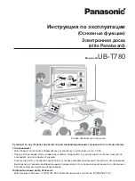
background image

87

11.1. CONTROL Board

1

4

UB-5838C / UB-5338C

CONTROL Board

Note : N.M. means “ Not Mounted”.

SBD[15-0]

SBD[4]

DD[15]

DD[14]

DD[13]

DD[12]

DD[11]

DD[10]

DD[9]

DD[8]

DD[7]

DD[6]

DD[5]

DD[4]

DD[3]

DD[2]

DD[1]

DD[0]

DBA[1]

DBA[0]

DA[12]

DA[11]

DA[10]

DA[9]

DA[8]

DA[7]

DA[6]

DA[5]

DA[4]

DA[3]

DA[2]

DA[1]

DA[0]

DBA[0]

DBA[1]

DA[10]

DA[0]

DA[1]

DA[2]

DA[3]

DA[4]

DA[5]

DA[6]

DA[7]

DA[8]

DA[9]

DA[11]

DA[12]

SBA[13-0]

SBA[0]

SBA[2]

SBA[3]

SBA[4]

SBA[5]

SBA[6]

SBA[7]

SBA[8]

SBA[9]

SBA[10]

SBA[11]

SBA[12]

SBA[13]

SBA[13]

SBA[12]

SBA[11]

SBA[10]

SBA[9]

SBA[8]

SBA[7]

SBA[3]

SBA[8]

SBA[7]

SBA[6]

SBA[5]

SBA[3]

SBA[2]

SBA[1]

SBD[0]

SBD[1]

SBD[2]

SBD[3]

SBD[4]

SBD[5]

SBD[15-0]

SBD[10]

SBD[9]

SBD[8]

SBD[14]

SBA[13]

SBA[12]

SBA[11]

SBA[10]

SBA[9]

SBA[0]

DQML

DQMU

WE

SBD[15-0]

SDCLK

CAS

RAS

DD[1]

DD[2]

DD[3]

DD[4]

DD[5]

DD[6]

DD[7]

DD[0]

CKE

DD[15]

DD[14]

DD[13]

DD[12]

DD[11]

DD[10]

DD[9]

DD[8]

DD[0]

DD[1]

DD[2]

DD[3]

DD[4]

DD[5]

DD[6]

DD[7]

DD[8]

DD[9]

DD[10]

DD[11]

DD[12]

DD[13]

DD[14]

DD[15]

SBD[0]

SBD[1]

SBD[3]

SBD[2]

SBD[5]

SBD[6]

SBD[7]

SBD[8]

SBD[9]

SBD[10]

SBD[11]

SBD[12]

SBD[13]

SBD[15]

SBD[14]

SBA[1]

SBA[4]

SBD[11]

SBD[12]

SBD[13]

SBD[15]

SBD[7]

SBD[6]

SBD[0]

SBD[1]

SBD[2]

SBD[3]

SBD[4]

SBD[5]

SBD[6]

SBD[7]

SBD[8]

SBD[9]

SBD[10]

SBD[11]

SBD[12]

SBD[13]

SBD[14]

SBD[15]

SBA[4]

SBA[5]

SBA[6]

SBA[2]

SBA[1]

SBA[0]

SDCLK

DQML

WE

CAS

RAS

DQMU

CKE

+3.3VDD

GND

GND

GND

GND

+3.3VDD

NSYSRST

1:1F;3:7B;4:6B

USBDINT1

3:7C

USBDINT0

3:7D

USBHINT

3:7B

NSPI1CS

2:8C

C68

7p

GND

+3.3VDD

+1.8VDD

C43

220p

R170

1.5k

C41

220p

GND

+3.3VDD

GND

GND

+3.3VDD

+1.8VDD

R74

33

NWR

3:7B;4:6B

NRD

3:7B;4:6B

R73

33

ROMWP

1:4B

NSYSRST

1:4C;3:7B;4:6B

NUSBHCS

3:7B

NKEYCS

4:5B

NUSBDCS

3:7D

R112

22

R111

22

R110

22

R55

22

R56

22

R57

22

GND

R71

33

R72

33

R24

10k

+3.3VDD

GND

+3.3VDD

SBD[15-0]

3:7C;4:6C

GND

C67

7p

SBA[13-0]

3:7B;3:7B;4:5B

CN1

1

2

3

4

5

6

7

8

9

10

11

12

13

14

15

16

17

18

19

20

GND

+3.3VDD

GND

+5VCC

GND

R200

4.7k

R201

1k

R203

4.7k

R205

4.7k

NLCDCS

4:5B

NRTCINT

4:7B

ADCLK1

2:8C

SHD1

2:8C

NSI

1:4C;2:8D

CISCLK

2:8C

SPICLK

1:7E;2:8C

SPIDO

1:7E;2:8D

VIDEO[0]

2:8C

VIDEO[1]

2:8C

VIDEO[2]

2:8C

VIDEO[3]

2:8C

VIDEO[4]

2:8B

VIDEO[5]

2:8B

VIDEO[6]

2:8B

VIDEO[7]

2:8B

DACSCL

2:5D

DACSDA

2:5D

RLED

2:8D

GLED

2:8D

BLED

2:8D

HWAKEUP

3:7A

HSUSPEND

3:7A

NDPSEL

3:7A

RTCCS

4:9B

NRTCSCK

4:9B

RTCDATA

4:9B

PDOWN1

2:5D

PDOWN2

2:5D

INA

2:5E

TDA

2:5E

INB

2:5E

TDB

2:5E

HOME1

2:5F

HOME2

2:5F

R224

10k

+3.3VDD

R226

10k

R227

10k

R229

10k

R230

10k

R233

10k

R235

10k

R238

10k

R240

10k

R241

10k

R242

10k

R243

10k

R244

10k

R246

10k

R247

10k

R250

10k

R251

10k

R252

10k

R253

10k

R254

10k

R255

10k

R256

10k

R257

10k

R259

10k

R215

10k

R216

10k

R217

10k

R218

10k

R220

10k

R221

10k

R223

10k

VBUS

1:6E

SDEXIST

1:7E

R23110k

R234

10k

R236

10k

R239

10k

R211

10k

R197

10k

R176

10k

R181

10k

R183

10k

R182

10k

R188

10k

R212

10k

R172

10k

R179

10k

R207

10k

R206

10k

R198

10k

R196

10k

R204

10k

R185

10k

R174

10k

R210

10k

R199

10k

R184

10k

R190

10k

R19510k

R186

10k

R202

10k

R180

10k

R171

10k

R193

10k

R187

10k

R19410k

R178

10k

R19210k

+3.3VDD

R58

22

R40

22

R41

22

R42

22

R43

22

R44

22

R45

22

R46

22

R47

22

R48

22

R49

22

R50

22

R51

22

R52

22

R53

22

R54

22

R3

10k

R28

10k

R33

10k

R35

10k

R38

10k

R76

10k

R79

10k

R82

10k

R85

10k

R88

10k

R91

10k

R121

10k

R129

10k

R132

10k

R133

10k

R4

10k

R95

33

R96

33

R97

33

R94

33

R93

33

R98

33

R99

33

R100

33

R101

33

R102

33

R103

33

R104

33

R105

33

R106

33

R107

33

R108

33

R59

33

R61

33

R62

33

R63

33

R64

33

R65

33

R66

33

R67

33

R68

33

R69

33

R70

33

R60

33

R114

33

R115

33

R116

33

R117

33

R118

33

R119

33

R120

33

R113

33

R31

10k

R32

10k

GND

+3.3VDD

NSDCS

1:7E

R75

33

ROMWP

1:1E

ROMRDY

1:1F

ROMRDY

1:4B

+3.3VDD

GND

R36

33

R39

33

R77

10k

+3.3VDD

R78

10k

R80

10k

R81

10k

R83

10k

R84

10k

R86

10k

R87

10k

R89

10k

R90

10k

R92

10k

R109

10k

R122

10k

R128

10k

R130

10k

R131

10k

R142

10k

R143

10k

R144

10k

R145

10k

R146

10k

R147

10k

R29

10k

R30

10k

R34

10k

+3.3VDD

R16

10k

R13

10k

R15

10k

R17

10k

R18

10k

R19

10k

R20

10k

R21

10k

R22

10k

R23

10k

R1

10k

R2

10k

R25

10k

R26

10k

R27

10k

NSDCS

1:1D

SPIDO

1:8C;2:8D

SPICLK

1:8C;2:8C

SPIDI

1:7E;2:8D

SPIDI

1:8C;2:8D

+3.3VDD

GND

SDEXIST

1:9C

SDWP

1:4B

SDWP

1:7E

+3.3VDD

GND

R273

47k

R272

47k

R222

47k

R225

47k

R228

47k

R232

47k

R237

47k

R219

47k

+3.3VDD

FG-SD

R14810k

+3.3VDD

GND

R149

22

R261

0

ERJ6GEY0R00V

R260

0

ERJ6GEY0R00V

R262

0

ERJ6GEY0R00V

+3.3VDD

GND

R177

10k

R173

22

R152

0

R150

10k

R151

10k

+3.3VDD

R14

33

R153

33

R154

33

R155

33

R156

33

R157

33

R158

33

R159

33

R160

33

R161

33

R162

33

R163

33

R164

33

R165

33

R166

33

R167

33

R168

33

R169

33

R263

33

R264

33

R265

33

R266

33

R267

33

R268

33

R269

33

R270

33

R271

33

R245

33

R248

33

R249

33

GND

GND

R209

100k

GND

VBUS

1:9C

R123

33

R124

33

R125

33

R126

33

R127

33

CL3

CL4

GND

CL1

CL2

R213

10k

R214

10k

C188

15p

C189

15p

C190

15p

C191

15p

C192

15p

C193

15p

C12

1n

C197

1n

GND

NSI

1:8B;2:8D

R493

10k

R494

10k

R495

10k

R496

10k

+3.3VDD

R497

10k

R498

10k

+3.3VDD

R499

10k

+3.3VDD

C17

1n

C315p

C215p

C515p

C1315p

C1515p

C1615p

C7615p

C7715p

C7815p

C7915p

C8

100n

R5

56

R6

56

R7

56

R8

56

R9

56

R10

56

R11

56

R12

56

R134

56

R135

56

R136

56

R137

56

R138

56

R139

56

R140

56

R141

56

CL20

CL21

CL22

CL23

CL24

CL25

CL26

CL27

R459

22

R460

22

R461

22

R462

22

R454

22

R455

22

R456

22

R457

22

R458

22

C72100n

C74100n

C1

100n

C4

100n

C6

100n

C7

100n

C9

100n

C10

100n

C11

100n

C14

100n

C19

100n

C20

100n

C40

100n

C61100n

C62

100n

C64

100n

C66

100n

C71

100n

C73

100n

L54

J0JHC0000046

L1

L2

L3

L4

L5

R507

0

R508

0

R509

0

C1ZBZ0002994

IC5

1

CLKIN

2

NC1

3

SS%

4

GND

5

SSON

6

CLKOUT

7

VDD

8

NC2

H1A4805B0023

X1

1

ENABLE

3

OUT

4

VDD

2

GND

C0JBAE000321

IC1

1B

2

A

3

GND

5

VCC

4

Y

CN3

K1NA09E00076

1

1

2

2

3

3

4

4

5

5

6

6

7

7

8

8

9

9

13

12

WP

10

Detect

11

Common

C1ZBZ0002831

IC4

PRIO00

D16

PRIO01

E16

PRIO02

E17

PRIO03

E18

PRIO04

F16

PRIO05

F17

PRIO06

F18

PRIO07

G16

PRIO08

G17

PRIO09

G18

PRIO10

H16

PRIO11

H17

PRIO12

H18

PRIO13

J16

PRIO14

J17

PRIO15

J18

PRIO16

K16

PRIO17

K17

PRIO18

K18

PRIO19

L16

PRIO20

L17

PRIO21

L18

PRIO22

M16

PRIO23

M17

PRIO24

M18

PRIO25

N16

PRIO26

N17

PRIO27

N18

PRIO28

P16

PRIO29

P17

PRIO30

P18

PRIO31

R16

*RESET

D18

XIN

T1

XOUT

P2

TEST

D17

*TRST

B18

TCK

A18

TMS

C18

TDI

B17

TDO

C17

SADCLK

V4

SCLK1

U3

SCLK2

V3

SD00

R2

SD01

K2

SD02

K3

SD03

H2

SD04

U2

SD05

J2

SD06

V2

SD07

K1

SSEN

T3

CCDCLK00

T6

CCDCLK01

U6

CCDCLK02

V6

CCDCLK03

T5

CCDCLK04

U5

CCDILL00

V5

CCDILL01

T4

CCDILL02

U4

SPICLK

A13

SPIDO

B12

SPIDI

A12

SMOT00

G3

SMOT01

G2

SMOT02

G1

SMOT03

J3

SMOT04

H3

SMOT05

H1

SMOT06

R3

GPIO00

C15

GPIO01

B15

GPIO02

A15

GPIO03

C14

GPIO04

B14

GPIO05

A14

GPIO06

C13

GPIO07

B13

RXD

A17

TXD

A16

*RTS

B16

*CTS

C16

C1ZBZ0002831

IC4

VDD33_01

N15

VDD33_02

M15

VDD33_03

J15

VDD33_04

G15

VDD33_05

F15

VDD33_06

D13

VDD33_07

D12

VDD33_08

D9

VDD33_09

D7

VDD33_10

D6

VDD33_11

F4

VDD33_12

G4

VDD33_13

K4

VDD33_14

M4

VDD33_15

R4

VDD33_16

R6

VDD33_17

R7

VDD33_18

R10

VDD33_19

R12

VDD33_20

R13

VSS33_01

L12

VSS33_02

K12

VSS33_03

K15

VSS33_04

J12

VSS33_05

H12

VSS33_06

G11

VSS33_07

G10

VSS33_08

D10

VSS33_09

G9

VSS33_10

G8

VSS33_11

H7

VSS33_12

J7

VSS33_13

K7

VSS33_14

L7

VSS33_15

M7

VSS33_16

M8

VSS33_17

R9

VSS33_18

M9

VSS33_19

M10

VSS33_20

M11

VDDA33_01

J1

VDDA33_02

V1

VSSA33_01

H4

VSSA33_02

T2

VDD18_01

P15

VDD18_02

L15

VDD18_03

H15

VDD18_04

E15

VDD18_05

D15

VDD18_06

D14

VDD18_07

D11

VDD18_08

D8

VDD18_09

D5

VDD18_10

D4

VDD18_11

E4

VDD18_12

J4

VDD18_13

L4

VDD18_14

R5

VDD18_15

R8

VDD18_16

R11

VDD18_17

R14

VDD18_18

R15

VSS18_01

M12

VSS18_02

L11

VSS18_03

K11

VSS18_04

J11

VSS18_05

H11

VSS18_06

G12

VSS18_07

J10

VSS18_08

H10

VSS18_09

J9

VSS18_10

H9

VSS18_11

G7

VSS18_12

H8

VSS18_13

J8

VSS18_14

K8

VSS18_15

K10

VSS18_16

L8

VSS18_17

L9

VSS18_18

L10

DDP

N1

DDM

M3

RDP

M1

RDM

L2

RREF

R1

RPUDP

M2

VDDUA33

L3

VSSUA33

L1

VDDUC33

P1

VSSUC

U1

VDDUA18

N2

VSSUA18

N3

VDDUC18

P3

VSSSW

N4

VDDDIG18

P4

VSSDIG18

K9

C1ZBZ0002831

IC4

DA00

V13

DA01

U12

DA02

V12

DA03

V11

DA04

V7

DA05

U7

DA06

T7

DA07

V8

DA08

U8

DA09

T8

DA10

U13

DA11

V9

DA12

U9

DBA00

U14

DBA01

V14

*DRAS

V15

*DCAS

U15

DCLK

V10

DCKE

T9

SBA00

A3

SBA01

A2

SBA02

A1

SBA03

B3

SBA04

B2

SBA05

B1

SBA06

C3

SBA07

C2

SBA08

C1

SBA09

D3

SBA10

D2

SBA11

D1

SBA12

E2

SBA13

E1

SBACK

A4

SBWR

C9

SBRD

A10

MEM00

E3

MEM01

F3

MEM02

F2

MEM03

F1

DD00

R18

DD01

R17

DD02

T18

DD03

T17

DD04

U18

DD05

V18

DD06

U17

DD07

V17

DD08

T10

DD09

U11

DD10

T11

DD11

T12

DD12

T13

DD13

T14

DD14

T15

DD15

T16

DQM00

U16

DQM01

U10

*DWE

V16

SBD00

B9

SBD01

A9

SBD02

C8

SBD03

B8

SBD04

A8

SBD05

C7

SBD06

B7

SBD07

A7

SBD08

C6

SBD09

B6

SBD10

A6

SBD11

C5

SBD12

B5

SBD13

A5

SBD14

C4

SBD15

B4

SBCS00

C12

SBCS01

C11

SBCS02

B11

SBCS03

A11

SBCS04

C10

SBCS05

B10

C3FBND000315

IC2

1

A15

2

A14

3

A13

4

A12

5

A11

6

A10

7

A9

8

A8

9

A19

10

A20

11

*WE

12

*RESET

13

NC

14

*WP/ACC

15

RY/*BY

16

A18

17

A17

18

A7

19

A6

20

A5

21

A4

22

A3

23

A2

24

A1

25

A0

26

*CE

27

VSS1

28

*OE

29

DQ0

30

DQ8

31

DQ1

32

DQ9

33

DQ2

34

DQ10

35

DQ3

36

DQ11

37

VCC

38

DQ4

39

DQ12

40

DQ5

41

DQ13

42

DQ6

43

DQ14

44

DQ7

45

DQ15/A-1

46

VSS2

47

*BYTE

48

A16

R175

3.09k

R191

40.2

R189

40.2

C21

100n

C22

100n

C23

100n

C24

100n

C25

100n

C26

100n

C27

100n

C28

100n

C29

100n

C30

100n

C31

100n

C32

100n

C44

100n

C45

100n

C46

100n

C47

100n

C48

100n

C49

100n

C50

100n

C51

100n

C52

100n

C53

100n

C54

100n

C55

100n

C42

100n

C75

1u

L48

J0JGC0000020

L53

0

R512

10k

R513

10k

R514

10k

R515

10k

R516

10k

LCDDET

4:7B

SCANNERDET

2:3A

ROMA21

1:1F

R520

10k

GND

ROMA21

1:8C

R521

33

C3ABRY000039

IC3

1

VDD1

2

DQ0

3

VDDQ1

4

DQ1

5

DQ2

6

VSSQ1

7

DQ3

8

DQ4

9

VDDQ2

10

DQ5

11

DQ6

12

VSSQ2

13

DQ7

14

VDD2

15

LDQM

16

*WE

17

*CAS

18

*RAS

19

*CS

20

BA0

21

BA1

22

A10/AP

23

A0

24

A1

25

A2

26

A3

27

VDD3

28

VSS1

29

A4

30

A5

31

A6

32

A7

33

A8

34

A9

35

A11

36

A12

37

CKE

38

CLK

39

UDQM

40

NC

41

VSS2

42

DQ8

43

VDDQ3

44

DQ9

45

DQ10

46

VSSQ3

47

DQ11

48

DQ12

49

VDDQ4

50

DQ13

51

DQ14

52

VSSQ4

53

DQ15

54

VSS3

L55

0

C198

1u

TRST

TDI

TMS

TCK

TDO

nRESET

+5v

TXD

RTS

RXD

CTS

DG

JTAG Connector (For CPU)

RS232C IF

Connector For SD Memory Card

47K

D-

D+

1005

1005

1005

1005

1005

1005

1005

1005

1005

1005

1005

1005

1005

1005

1005

1005

1005

1005

1005

1005

1005

1005

1005

1005

1005

N.M.

N.M.

N.M.

N.M. 
N.M.

1

1

N.M.

N.M.

N.M.

N.M.

N.M.

N.M.

N.M.

N.M.

N.M.

N.M.

N.M.

N.M.

N.M.

N.M.

N.M.

N.M.

N.M.

N.M.

N.M.

78

56

4

2

13

78

56

4

2

13

F

D

A

B

E

C

F

D

A

B

E

C

N.M.

Summary of Contents for UB-5838C

Page 1: ...Panasonic Communications 2009 Unauthorized copying and distribution is a violation of law Order Number KM70906495CE Category Number H19 Electronic Board Model No UB 5838C Model No UB 5338C...

Page 2: ...6 6 Control Box Unit 48 6 7 Screen Roller 54 6 8 Screen Guide R and Screen Guide L 57 6 9 Screen Film 59 6 10 Frame 64 7 Service Mode 69 7 1 How to enter the service mode 69 7 2 Service Mode and Init...

Page 3: ...C Live Neutral of the plug with a jumper wire 3 Turn ON the power switch 4 Measure the resistance value with an ohmmeter between the jumpered AC plug and each exposed metal cabinet part such as screwh...

Page 4: ...Ag and Copper Cu This model and others like it manufactured using lead free solder will have PbF stamped on the PCB For service and repair work we suggest using the same type of solder Distinction of...

Page 5: ...lead mercury cadmium hexavalent chromium polybrominated biphenyls and polybrominated diphenyl ethers have been either totally eliminated or limited to the concentration level below maximum allowed Co...

Page 6: ...guished by the Areas Countries Distinction Mark printed on the name plate In this manual the Areas Countries Distinc tion Mark is used to distinguish this difference When servicing repairing or handli...

Page 7: ...95 F Humidity 30 to 80 RH Ambient Storage Conditions Temperature 20 to 60 C 4 to 140 F Humidity 15 to 80 RH Display 1 8 inch Color LCD Battery for Clock Lithium Coin Battery CR2032 x 1 PC Interface Fu...

Page 8: ...ure 20 to 60 C 4 to 140 F Humidity 15 to 80 RH Display 1 8 inch Color LCD Battery for Clock Lithium Coin Battery CR2032 x 1 PC Interface Full Speed USB 2 0 Note This unit does not function with Hi Spe...

Page 9: ...9 2 3 External View...

Page 10: ...10 2 4 Control Panel Operation...

Page 11: ...11 2 5 External Dimensions 2 5 1 UB 5838C...

Page 12: ...12 2 5 2 UB 5338C...

Page 13: ...and others Locations 7 POWER Board 8 CONTROL Board 11 Battery Power Switch AC Inlet 10 LCD 9 PANEL Board 3 HOME SENSOR Board 4 MOTOR DRIVE Board 5 Motor 1 Scanner Assy 2 SCANNER Board Screen Feed Dir...

Page 14: ...out with a printer 2 SCANNER Board This board converts the signals into image digital signals and then will transmit the digital signals to the CONTROL Board 3 HOME SENSOR Board This board detects th...

Page 15: ...s a sophisticated piece of equipment which somewhat depends on the surrounding conditions for optimum operation Attention to the following will result in more reliable and quality performance This mod...

Page 16: ...Joints UB 5338C has 8 Joints Note 1 When handling the screen unit grasp the side cover on either side of screen Do not grasp the screen film surface as this may scratch it 2 When removing the shippin...

Page 17: ...17 3 3 2 Included Accessories The package includes the parts for setting up the unit shown below Make sure that all of these parts are included in the package before proceeding...

Page 18: ...material and other packing materials do not strike the screen film Contact may damage the screen film 1 Collapse the shipping box 2 Remove the protective plastic bag and lay down the unit onto the sh...

Page 19: ...ust the position of the Wall mounting Fixtures Note The 4 Wall mounting screws are not included with the elec tronic board Please purchase M6 size screws appropriate for your wall 1 Remove the 4 rivet...

Page 20: ...ttach the optional Stand to the unit Each Stand has 3 holes A B C 1 Attach the Stand to the unit with the locking caster up 2 When attaching the unit to the Stand at normal height 1 830 mm 6 2 32 tigh...

Page 21: ...Power Cord Securely fit the included Power Cord in the AC inlet of the control box 3 Remove the battery protection sheet 1 Turn the power switch on The time set up screen is displayed automatically w...

Page 22: ...22 3 4 3 Operation Check Procedure After assembling the unit and setting the time perform the procedures presented in the following table to make sure it functions properly...

Page 23: ...ve Assembly Steps Sec 3 3 1 to Sec3 3 5 in reverse order to repack the unit and accessories Note When handling the screen unit grasp the side cover on either side of screen Do not grasp the screen fil...

Page 24: ...se heat smoke or fire 3 6 1 1 Necessary Tools and Parts not included with the product 1 Drill 2 Screwdriver 3 Measuring tape 4 Level 5 8 screws M6 size 3 6 1 2 Before Starting 1 Make sure that the wal...

Page 25: ...the unit will not be crooked 3 The lateral tolerance of the hole position of the Wall mounting Fixture is 1 5 mm 1 16 1 Ensure that the wall is strong enough to support the unit For UB 5838C 1 373 N...

Page 26: ...t they will not become loose 3 When drilling the holes and installing the wall mounting fixtures follow the procedure in Wall Types and Installation Procedures 4 Install the Wall mounting Fixtures usi...

Page 27: ...ons for the particular stud plugs used 2 Insert a stud plug in each hole 3 Insert the bolt through a hole in the Wall mounting Fixture and tighten until the Wall mounting Fixture is securely fixed to...

Page 28: ...ores are needed Insert the wood screw through the hole in the Wall mount ing Fixture and tighten until the Wall mounting Fixture is securely fixed to the wall For the correct hole size refer to the in...

Page 29: ...into contact with the film As shown on the Fig 4 1 1 the Home Marker is attached on the lower position of the scrolled Screen Film so as to tell Panaboard the screen home position required to feed the...

Page 30: ...the Contact Image Sensors CISs through the Lens The CISs will convert the light into electrical signals and then will transmit the signals to the SCANNER Board Then the SCANNER Board will convert the...

Page 31: ...d 2 Check the connection between CN4 CONTROL Board and CN800 MOTOR DRIVE Board 3 Check the connection between CN604 SCANNER Board and CN801 MOTOR DRIVE Board 4 Check the connection between CN605 SCANN...

Page 32: ...y 2 Check the connection between CN606 SCANNER Board and CN5 CONTROL Board 3 Check the connection between CN4 CONTROL Board and CN800 MOTOR DRIVE Board 4 Check the connection between CN604 SCANNER Boa...

Page 33: ...h SD memory card specifications using the formatting software that can be downloaded from the following site http panasonic jp support global cs sd download sd_formatter html U306010 Unavailable space...

Page 34: ...ing to the Operation Instructions for the printer U314227 Printer Paper Jam A paper jam in the printer occurred 1 Remove the jamming paper in the printer U314228 Printer Working The printer is working...

Page 35: ...06208 U407209 Removed USB Flash Memory Device The USB Flash Memory Device was removed while scanning 1 Set the USB Flash Memory Device and then restart scanning U413010 In short supply of Memory to sc...

Page 36: ...D 1 Remove the USB Flash Memory Device or SD Memory Card from the unit Panaboard and then check whether that removal changes the illustration to the printer s Defects in the printed image The amount o...

Page 37: ...tions of IC700 and IC701 on the PANEL Board 5 Check the soldering conditions of IC16 IC17 and IC20 on the CONTROL Board 6 Check the following signals on the PANEL Board 1 CL728 5 0 V 2 CL729 3 3 V 7 R...

Page 38: ...y Device or SD Memory Card is not recognized 1 The USB Flash Memory Device or SD Memory Card is not available for this unit 1 Check whether the device or card is available for the unit For information...

Page 39: ...the model See Sec 7 2 2 Set the application areas countries See Sec 7 2 2 Clear the shading back up data See Sec 7 2 Check the scanning function See Sec 3 4 MOTOR DRIVE Board Component parts on MOTOR...

Page 40: ...Cover 6 1 1 Cover Lower Cover L and Cover Lower L 1 Remove the 2 screws A and 2 screws B 2 Remove the Cover Lower Assy 3 Remove the 2 screws C 4 Remove the Cover L in the direction of the arrow 5 Rem...

Page 41: ...er Upper R and Cover R 1 Remove the 2 screws A 2 Remove the Cover Upper 3 Remove the 2 screws B 4 Remove the Cover Upper L 1 Remove the 2 screws A Then remove Cover Upper R 2 Remove the screw B Then r...

Page 42: ...forming these section procedures remove the following parts 1 Remove the Cover Lower Assy See 6 1 1 2 Remove the Cover R See 6 1 3 1 Remove the 4 screws A Then remove the Cover Lower R 2 If necessary...

Page 43: ...forming these section procedures remove the following part Remove the Cover L See 6 1 1 1 Remove the 3 screws A and 2 screws B Then remove the Scanner Board Cover 2 Remove the 7 cable harnesses from t...

Page 44: ...parts 1 Remove the Cover Lower Assy Cover L and Cover Lower L See 6 1 1 2 Remove the Scanner Board Cover See 6 2 1 3 Remove the 2 cable harnesses CN604 CN606 from the SCANNER Board See 6 2 1 1 Remove...

Page 45: ...sy Cover L and Cover Lower L See 6 1 1 1 Remove the Motor Cable Harness 2 Remove the 2 screws A and then remove the Motor Drive Unit 3 Remove the 3 screws B to release the Top Drive Plate Gear and Pol...

Page 46: ...he Cover Lower Assy Cover L and Cover Lower L See 6 1 1 2 Remove the Motor Drive Unit See 6 3 1 Remove the 4 screws A and then remove the Shield Cover 2 Remove the Sensor Cable Harness CN803 from the...

Page 47: ...1 2 Remove the Shield Cover See 6 4 5 Remove the 2 screws C to release the Sensor Cover from the Sensor Holder Plate with HOME SENSOR Board 6 Remove the 2 screws D Then remove the HOME SENSOR Board f...

Page 48: ...CN604 CN606 out of the 7 cable harnesses from the SCANNER Board Then release the 2 cable harnesses from the clamps See 6 2 3 Remove the HOME SENSOR Board See 6 4 1 Remove the screw A and screw B Then...

Page 49: ...2 Release the cable from the 3 clamps 3 Remove the 2 screws A and then remove the CP Support Plate 4 Remove the 6 screws Then remove the Control Panel Support Stays R and L on both sides 5 Remove the...

Page 50: ...ews and Lower Panel If necessary remove the SD Cover 7 Remove the 7 screws and then remove the Control Box Cover 8 Remove the cable harness with black tape attached and the cable harness with gray tap...

Page 51: ...the Rear Cover 11 Release the 2 cables from the clamps 12 Pull the cable through the aperture 1 Remove the screw A and USB Earth Ground Plate 2 Remove the 5 screws B and 2 cable harnesses from the CON...

Page 52: ...emove the LCD Be sure to release the 2 hooks when removing the LCD from the Operation Panel 1 Remove the Battery Holder from the Control Box Unit 2 Remove the Panel Cable Harness from the PANEL Board...

Page 53: ...e the 3 screws A and the screw B Then remove the Power Box Cover 2 Remove the 4 screws on the POWER Board 3 Remove the screw that supports the Ground lug 4 Remove the 2 cable harnesses from the POWER...

Page 54: ...Cover Upper L See 6 1 2 3 Remove the Cover Upper R and Cover R See 6 1 3 4 Remove the Cover Lower R and Roller Unit Cover See 6 1 4 5 Remove the Scanner Assy See 6 2 2 6 Remove the Motor Drive Unit S...

Page 55: ...ay cause the pin to insert into the Roller Pipe to disable the roller attachment 5 Remove the screw A and then remove the Screen Guide Upper 6 Remove the 2 screws B and then remove the Bearing Holder...

Page 56: ...te 1 Must not remove Rings A on both sides of the Screen Sub roller That removal may cause the pin to insert into the Roller Pipe to disable the roller attachment 2 When installing the Screen Sub roll...

Page 57: ...ower L See 6 1 1 2 Remove the Cover Upper and Cover Upper L See 6 1 2 3 Remove the Cover Upper R and Cover R See 6 1 3 4 Remove the Cover Lower R See 6 1 4 Prepare for the bench that fills the specifi...

Page 58: ...B and 6 screws C Then remove the Rear Side Cover R 2 Remove the 4 screws D and 4 screws E Then remove the 4 Screen Guides R Screen Guide L 1 Remove the 2 screws F 2 screws G 6 screws H 2 screws I and...

Page 59: ...6 1 3 4 Remove the Cover Lower R and Roller Unit Cover See 6 1 4 5 Remove the Scanner Assy See 6 2 2 6 Remove the Motor Drive Unit See 6 3 1 Remove the 2 screws A and then remove the 2 Screen Guides...

Page 60: ...B and then remove the Roller Tension Plate Top Sub assy 9 Remove the 5 screws C and then remove the Base Plate Support on the lower side 10 Remove the Spring on the lower side 11 Remove the 2 screws...

Page 61: ...e sure to attach the side where the roller has the Bearing made of metal to the upper side of the unit This bearing is used as an earth connecting point for this unit by installing it to the unit Scre...

Page 62: ...62 15 Pull the Inner Panel L and Inner Panel R in the direction of the arrows to remove them not to give a damage to the Screen Film 16 Separate the Screen Film from the Frame Unit...

Page 63: ...nel L and Inner Panel R into the Screen Film Then while keeping the Tip A of the Inner Panel L in contact with that of the Inner Panel R push down the panels in the direction of the arrow B so as not...

Page 64: ...r R See 6 1 3 4 Remove the Cover Lower R and Roller Unit Cover See 6 1 4 5 Remove the Scanner Assy See 6 2 2 6 Remove the Motor Drive Unit See 6 3 7 Remove the MOTOR DRIVE Board See 6 5 8 Remove the C...

Page 65: ...e the screw Then remove the Panel Hinge Sleeve and Hing Shaft on the upper position 3 Remove the screw Then remove the Panel Hinge Sleeve and Hing Shaft on the lower position 4 Divide the Frame into t...

Page 66: ...n Sec 6 8 2 Remove the 4 Screen Guides R See Screen Guide R in Sec 6 8 3 Remove the 2 screws and then remove the Rear Cover R 4 If necessary remove the 4 screws F screw G and 2 screws H Then remove th...

Page 67: ...the 2 screws G 6 screws H and 2 screws F Then remove the Rear Side Cover L 2 Remove the 2 screws I If necessary remove the 2 screws J and then remove the 2 Screen Guides L 3 Remove the 2 screws and th...

Page 68: ...cessary remove the 4 screws K screw M and 2 screws L and then remove the Rear Cover Holder 1 Rear Cover Holder 2 and Wall Mount Under Plate 5 If necessary remove the screw N and then remove the Home S...

Page 69: ...ting the application area country on this unit Panaboard the screen for the Intial Settting Mode is displayed on the LCD when turning on the power 7 1 1 Method 1 While holding down the Mode Set up and...

Page 70: ...or restart the power and then check that the initial screen Fig 7 1 2 1 is displayed on the LCD Step 2 Push the Set up Key to change the screen Fig 7 1 2 2 on the LCD Step 3 Push the Set up Key a few...

Page 71: ...4 Push the Advance Key to change the screen Fig 7 1 2 4 on the LCD Step 5 While pushing the Advance Key push the Mode and Set up Keys for one second or more Then check that the screen for Service Mode...

Page 72: ...nable us to select and set Menu and Item for Service Mode 7 2 1 Service Mode Enter the Service Mode following Sec 7 1 How to enter the service mode Note Without setting the application area country th...

Page 73: ...Panaboard the screen for the Initial Setting Mode will be displayed on the LCD After selecting Board on the menu set the screen panel size Std or Wide for this unit with the Advance Key Then selectin...

Page 74: ...74 7 3 LCD Test Pattern Performing the LCD Pattern on the menu of the Service Mode will allow the following test patterns to be displayed on the screen due to the LCD diagnostics...

Page 75: ...75 7 4 Service Mode Operations The Service Mode operations are as follows When exiting the Service Mode turn off the power...

Page 76: ...ethyl alcohol 2 Do not use thinner benzine or cleaners containing abrasives or surfactants as this may result in discoloration or difficulty of erasing 3 Do not wipe the screen film with a dry cloth a...

Page 77: ...h your finger and peel off the dirty sheet white or gray sheet by pulling in the direction of the arrow Note 1 Be sure to peel off only one sheet white or gray sheet of the eraser 2 When the eraser be...

Page 78: ...l 1 then remove the battery holder 2 2 Remove the old battery and install the new one with the positive terminal upward Note Always use CR2032 batteries and be sure that the battery is inserted as ind...

Page 79: ...256 Mbit SDRAM IC3 24V 3 3V 1 8V 5V IC19 LCD IC700 IC701 IC704 IC16 IC17 OR IC1 32 Mbit ROM IC2 AND IC20 IC12 IC11 IC13 DSP DSP DSP LED CIS Serial IF System Bus IF Buffer Scanner IF Image Data Proces...

Page 80: ...80 9 2 Connection Diagram Power Unit POWER Board PANEL Board HOME SENSOR Board LED SCANNER Board CONTROL Board Printer USB Memory PC SD Memory MOTOR DRIVE Board Motor for Screen feed...

Page 81: ...PG Ground 4 4 PG Ground 5 5 INA Motor Drive Signal INA 6 6 TDA Motor Drive Signal TDA 7 7 INB Motor Drive Signal INB 8 8 TDB Motor Drive Signal TDB 9 9 AGND Ground 10 10 AGND Ground 11 11 PDOWN Curren...

Page 82: ...Data Differecial Signal D2 16 16 AGND Ground 17 17 D1P Image Data Differecial Signal D1 18 18 D1M Image Data Differecial Signal D1 19 19 D0M Image Data Differecial Signal D0 20 20 D0P Image Data Diffe...

Page 83: ...l D2 15 15 PSBD3 System Bus Data Signal D3 16 16 PSBD4 System Bus Data Signal D4 17 17 PSBD5 System Bus Data Signal D5 18 18 PSBD6 System Bus Data Signal D6 19 19 PSBD7 System Bus Data Signal D7 20 20...

Page 84: ...ntrol Signal Green 12 12 BLED LED Control Signal Blue 13 13 24V 24 V 14 14 24V 24 V 15 15 MGND Ground 16 16 MGND Ground CN600 CN601 CN602 CN603 SCANNER Board CIS Pin No Signal Name Description Remarks...

Page 85: ...Signal D1 13 13 D0 Data Signal D0 14 14 RDB Read Signal 15 15 WDB Write Signal 16 16 RS Register Select Signal 17 17 RSTB Reset Signal 18 18 CS1B LCD Chip Select Signal CN802 MOTOR DRIVE Board Motor P...

Page 86: ...86 11 Schematic Diagram Index 11 1 CONTROL Board 11 2 PANEL Board 11 3 SCANNER Board 11 4 MOTOR DRIVE Board 11 5 HOME SENSOR Board...

Page 87: ...6 R136 56 R137 56 R138 56 R139 56 R140 56 R141 56 CL20 CL21 CL22 CL23 CL24 CL25 CL26 CL27 R459 22 R460 22 R461 22 R462 22 R454 22 R455 22 R456 22 R457 22 R458 22 C72100n C74100n C1 100n C4 100n C6 100...

Page 88: ...88 2 4 UB 5838C UB 5338C CONTROL Board 7 8 5 6 4 2 1 3 7 8 5 6 4 2 1 3 F D A B E C F D A B E C Note N M means Not Mounted N M N M...

Page 89: ...0 ERJ6GEY0R00V R338 0 ERJ6GEY0R00V R339 0 ERJ6GEY0R00V R361 1 5k R396 47 R38310k R3801M R358 10k R36210k R367 33 R369 33 R372 33 R373 33 R374 33 R375 33 R376 33 R377 33 R379 33 R381 33 R382 33 R384 3...

Page 90: ...90 4 4 UB 5838C UB 5338C CONTROL Board Note N M means Not Mounted 7 8 5 6 4 2 1 3 7 8 5 6 4 2 1 3 F D A B E C F D A B E C N M N M RTC Power Circuit For 1 8V To POWER Board To PANEL Board Reset Circuit...

Page 91: ...4 7 L C 5 4 7 L C 6 4 7 L C 7 4 7 L C 8 4 7 L C 9 4 7 L C 0 5 7 L C 1 5 7 L C 0 6 7 L C 1 3 7 L C 2 3 7 L C 3 3 7 L C 4 3 7 L C 5 3 7 L C 6 3 7 L C 7 3 7 L C 4 8 7 L C 5 8 7 L C 6 8 7 L C 7 8 7 L C 8...

Page 92: ...635 100p C630 100p C634 100p C637 100p C625 CL630 8 2 6 L C 1 3 6 L C 9 2 6 L C V C V 3 3 3 1 6 L C 0 1 6 L 3 1 6 L V C V 3 3 V C V 3 3 V C V 3 3 6 1 6 L 9 1 6 L 3 0 6 N C 1 2 3 4 5 6 7 8 9 0 1 1 0 6...

Page 93: ...1 2 Y 1 7 1 4 A 2 8 1 1 Y 1 9 1 E O 2 0 2 C C V 35 100u C649 35 100u C645 IC603 1 S C 2 S E 3 TC 4 GND 5 CII 6 VCC 7 IS 8 DC 3 0 6 D 1 2 3 0 5 n 1 4 5 6 C 3 B D A C 5 4 N O R W P B 6 3 2 0 6 Q B C E 4...

Page 94: ...k R665 300k R666 300k R667 300k R662 V 3 3 300k R668 300k R670 10k R671 V 3 3 3 1 7 L C 4 1 7 L C 5 1 7 L C 6 1 7 L C 7 1 7 L C 8 1 7 L C 9 1 7 L C 6 0 6 C I 1 N E 2 1 N I D 3 2 N I D 4 C C V 5 D N G...

Page 95: ...C 7 2 8 L C 5 2 8 L C CL829 CL830 3 2 8 L C 0 0 2 0 1 8 R 1k R816 1 5k R817 200 R814 0 0 2 5 1 8 R 0 0 2 8 0 8 R D N G D N G D N G 1 2 8 L C 2 2 8 L C 0 0 8 C I A m m V 1 1 T U O 2 1 C N 3 A s R 4 2...

Page 96: ...009C GND GND GND GND GND GND 3 3V 3 3V CL901 CL903 4 7k R902 61 u01 209C GND CL902 CN900 1 2 3 CL904 22 R904 p001 05 109C 3 3V HOME GND To Motor Drive PCB CN803 e t o N d e t n u o M t o N s n a e m C...

Page 97: ...97 12 Printed Circuit Board Index 12 1 CONTROL Board 12 2 PANEL Board 12 3 SCANNER Board 12 4 MOTOR DRIVE Board 12 5 HOME SENSOR Board...

Page 98: ...CL19 R100 R101 R102 R103 R104 R105 R106 R107 R108 1 0 3 R 0 0 3 R 2 0 3 R 3 0 3 R 0 1 1 R R304 1 1 1 R R305 2 1 1 R R306 R113 R307 R114 R308 R115 R309 R116 7 1 1 R R118 1 0 5 R 9 1 1 R R310 R504 R311...

Page 99: ...CN605 R622 2 1 0 3 9 2 6 0 6 N C R623 R624 R625 R626 R627 9 2 6 R R630 R632 R633 R634 R635 R636 R638 R639 0 0 6 C 1 0 6 C 2 0 6 C 3 0 6 C 4 0 6 C 1 4 6 R 5 0 6 C 2 4 6 R 6 0 6 C 3 4 6 R 7 0 6 C 4 4 6...

Page 100: ...R801 9 0 8 C R802 CN803 1 3 1 0 8 C R803 2 0 8 N C 1 4 2 0 8 C 5 0 8 R C804 C803 C805 8 1 8 R C807 C808 2 1 8 R 6 0 8 C 3 1 8 R 4 1 8 R 5 1 8 R R816 R817 R809 R810 D800 1 1 8 R Q801 S 0 0 8 Q E 6 0 8...

Page 101: ...101 13 Exploded View and Replacement Parts List...

Page 102: ...102 13 1 Framework of Projected Diagram...

Page 103: ...103 13 2 Cabinet Unit...

Page 104: ...for UB 5838C Series ISO PS 11 PJKMC0041Z Cover Upper Std for UB 5338C Series ISO PS 12 PJKMC0050Z Cover Lower Wide for UB 5838C Series ISO PS 12 PJKMC0042Z Cover Lower Std for UB 5338C Series ISO PS 1...

Page 105: ...105 13 3 Motor Drive Unit Sensor Unit...

Page 106: ...otor for UB 5838C Series 12 L6HAYYYK0034 Stepping Motor for UB 5338C Series 13 PJDGC0249Z Wide Gear55 for UB 5838C Series 13 PJDGC0248Z Standard Gear60M05 for UB 5338C Series 14 PJZH0A7110J Plate Ashy...

Page 107: ...107 13 4 Control Box Unit...

Page 108: ...PJMEC0117Z Lcd Earth Sheet 32 PJBUC0099Z Lcd Earth Plate 33 K 103G R Clamp 34 PJMEC0069Z Power Box Cover 35 XYN4 F8FJ Screw 36 PJMEC0071Z Control Box Cover 38 PJJRC3018Y Power Supply Harness 44 EDS 12...

Page 109: ...109 13 5 Screen Feed Roller Unit...

Page 110: ...FJ Screw 14 XTW3 6LFJ Screw 15 PJUEC0400Z Top Left main plate 16 PJUEC0401Z Top Left Bearing keep plate 17 XTW3 10PFJ Screw 18 PJUEC0405Z Slide Plate 19 PJUEC0404Z Base Plate Support 20 PJUEC0403Z Und...

Page 111: ...111 13 6 Scanner Unit...

Page 112: ...30Z CIS under bracket 5 PJWU0A7100J Scanner sub Ashy 6 RTP3 8 3 B Screw 7 PJMCC0151Z CIS PCB holed plate 9 PJWP0A7140J Scanner Board 10 PJMCC0150Z CIS PCB cover plate 14 PJJRC3020Y CIS Harness 1 15 PJ...

Page 113: ...113 13 7 Panel Unit...

Page 114: ...lm STD for UB 5338C Series 4 XTW4 8LFJ Screw 5 PJHRC0458Z Inner Panel Holder 1 6 PJUEC0399Z Inner Panel Holder 2 7 PJZH0A7130J Inner Panel L WIDE for UB 5838C Series 7 PJZH0A7150J Inner Panel L STD fo...

Page 115: ...115 13 8 Frame Unit...

Page 116: ...C0289Y Horizontal Pipe L STD for UB 5338C Series 20 PJHRC0455Z Joint Holder 21 PJUCC0018Z Joint Plate 23 PJZH0A7100J Hinge L Ashy 24 XYN6 F12FJ Screw 25 XYN6 F30FJ Screw 26 XNG6EFJ Nut 27 XTW3 10PFJ S...

Page 117: ...117 13 9 Rear Cover Unit...

Page 118: ...en Film Guide 9 PJUAC0291Z Vertical Sub Frame 10 PJKZC0112Y Rear Side Cover R ISO PP 11 PJKZC0118Y Rear Cover R WIDE for UB 5838C Series 11 PJKZC0109Y Rear Cover R STD for UB 5338C Series 12 PJKZC0111...

Page 119: ...119 13 10 Packing...

Page 120: ...UB 5338C CN 15 PJKJC0003Z Wall Mount Plate 16 PJQXC0259Z Operating Instructions English for UB 5838C C A G T U UB 5338C C A G T U 16 PJQXC0271Z Operating Instrucrions French Spanish Tradi tional Chine...

Page 121: ...10W R33 ERJ3GEYJ103 10K 1 10W R34 ERJ3GEYJ103 10K 1 10W R35 ERJ3GEYJ103 10K 1 10W R36 ERJ3GEYJ103 10K 1 10W R38 ERJ3GEYJ103 10K 1 10W R40 ERJ3GEYJ220 22 1 10W R41 ERJ3GEYJ220 22 1 10W R42 ERJ3GEYJ220...

Page 122: ...J220 22 1 10W R111 ERJ3GEYJ220 22 1 10W R112 ERJ3GEYJ220 22 1 10W R113 ERJ3GEYJ330 33 1 10W R114 ERJ3GEYJ330 33 1 10W R115 ERJ3GEYJ330 33 1 10W R116 ERJ3GEYJ330 33 1 10W R117 ERJ3GEYJ330 33 1 10W R118...

Page 123: ...03 10K 1 10W R193 ERJ3GEYJ103 10K 1 10W R194 ERJ3GEYJ103 10K 1 10W R195 ERJ3GEYJ103 10K 1 10W R196 ERJ3GEYJ103 10K 1 10W R197 ERJ3GEYJ103 10K 1 10W R198 ERJ3GEYJ103 10K 1 10W R199 ERJ3GEYJ103 10K 1 10...

Page 124: ...ERJ3GEYJ473 47K 1 10W R273 ERJ3GEYJ473 47K 1 10W R274 ERJ3GEYJ470 47 1 10W R275 ERJ3GEYJ470 47 1 10W R276 ERJ3GEYJ470 47 1 10W R277 ERJ3GEYJ470 47 1 10W R278 ERJ3GEYJ470 47 1 10W R279 ERJ3GEYJ101 100...

Page 125: ...R2 18 2 1 16W R354 ERJ3EKF18R2 18 2 1 16W R355 ERJ3EKF18R2 18 2 1 16W R356 ERJ3EKF18R2 18 2 1 16W R357 ERJ3GEYJ473 47K 1 10W R358 ERJ3GEYJ103 10K 1 10W R359 ERJ3EKF27R0 27 1 16W R360 ERJ3EKF27R0 27 1...

Page 126: ...R432 ERJ3GEYJ470 47 1 10W R433 ERJ3GEYJ470 47 1 10W R434 ERJ3GEYJ470 47 1 10W R435 ERJ3GEYJ470 47 1 10W R436 ERJ3GEYJ470 47 1 10W R445 ERJ3GEYJ470 47 1 10W R446 ERJ3GEYJ220 22 1 10W R447 ERJ3GEYJ470...

Page 127: ...4 ECJ0EB1A104K 0 1 10V C25 ECJ0EB1A104K 0 1 10V C26 ECJ0EB1A104K 0 1 10V C27 ECJ0EB1A104K 0 1 10V C28 ECJ0EB1A104K 0 1 10V C29 ECJ0EB1A104K 0 1 10V C30 ECJ0EB1A104K 0 1 10V C31 ECJ0EB1A104K 0 1 10V C3...

Page 128: ...0 1 50V C110 ECJ1VF1H104Z 0 1 50V C111 ECJ1VF1H104Z 0 1 50V C113 F2G1C1000014 100 16V C115 ECJ1VC1H270J 27P 50V C117 ECJ1VF1H104Z 0 1 50V C118 ECJ1VF1H104Z 0 1 50V C119 ECJ1VC1H270J 27P 50V C120 ECJ1...

Page 129: ...04 ECJ1VC1H101J 100P 50V C205 ECJ1VF1H104Z 0 1 50V C206 ECJ1VF1H104Z 0 1 50V C207 ECJ1VF1H104Z 0 1 50V C208 ECJ1VF1H104Z 0 1 50V C209 ECJ1VF1H104Z 0 1 50V C210 ECJ1VF1H104Z 0 1 50V C211 ECJ1VF1H104Z 0...

Page 130: ...C9 C0JBAZ002811 IC IC10 C0ZBZ0000744 IC IC11 C0DBZYY00015 IC IC12 C0ZBZ0001432 IC IC13 C1DB00001308 IC IC14 C0DBCFG00013 IC IC15 C0EBE0000338 IC IC16 C0JBAZ002811 IC IC17 C0JBAZ002812 IC IC19 C1ZBZ000...

Page 131: ...3162V 31 6K 1 10W R639 ERJ3EKF1002 10K 1 10W R641 ERJ3GEYJ102 1K 1 10W R642 ERJ3GEYJ103 10K 1 10W R643 ERJ14YJ151U 150 1 4W R644 ERJ3GEYJ103 10K 1 10W R646 ERJ3GEYJ220 22 1 10W R647 ERJ3GEYJ220 22 1 1...

Page 132: ...104Z 0 1 50V C610 ECJ1VF1H104Z 0 1 50V C611 ECJ1VF1H104Z 0 1 50V C612 ECJ1VF1H104Z 0 1 50V C613 ECJ1VF1H104Z 0 1 50V C614 ECJ1VF1H104Z 0 1 50V C615 ECJ1VF1H104Z 0 1 50V C616 ECJ1VB1C105K 1 16V C617 EC...

Page 133: ...075 Filter L606 J0JHC0000075 Filter L607 G1A151E00003 Coil L608 J0JCC0000059 Inductor Coil L609 J0JCC0000059 Inductor Coil L610 J0JHC0000046 Filter L611 J0JCC0000059 Inductor Coil L612 J0JCC0000059 In...

Page 134: ...470 47 1 10W R744 ERJ3GEYJ202 2K 1 10W R745 ERJ3GEYJ103 10K 1 10W R746 ERJ3GEYJ470 47 1 10W R747 ERJ3GEYJ470 47 1 10W R748 ERJ3GEYJ470 47 1 10W R749 ERJ3GEYJ470 47 1 10W R750 ERJ3GEYJ470 47 1 10W R751...

Page 135: ...ECJ1VC1H101J 100P 50V C746 ECJ1VC1H101J 100P 50V C747 ECJ1VC1H101J 100P 50V C748 ECJ1VC1H101J 100P 50V C749 ECJ1VC1H101J 100P 50V C750 ECJ1VC1H101J 100P 50V C751 ECJ1VC1H101J 100P 50V C752 ECJ1VC1H10...

Page 136: ...104Z 0 1 50V C803 ECJ1VF1H104Z 0 1 50V C804 ECUX1H332KBV 3300P 50V C805 F2G1V1010023 2K 35V C806 ECJ1VF1H104Z 0 1 50V C807 ECJ1VF1H104Z 0 1 50V C808 ECJ1VF1H104Z 0 1 50V C809 F2G1A1010013 100 10V CN80...

Reviews: