2WAY SYSTEM
Control Functions
-
Outdoor Unit
1
- 8
1
3. Compressor Control
- Heating operation
The heating capacity is adjusted with this control. It also prevents abnormal high-pressure.
Operation pressure is able to be adjusted for existing old piping.
If area shift function is set, values below shift.
EEPROM setting in main outdoor unit
CODE : 4B
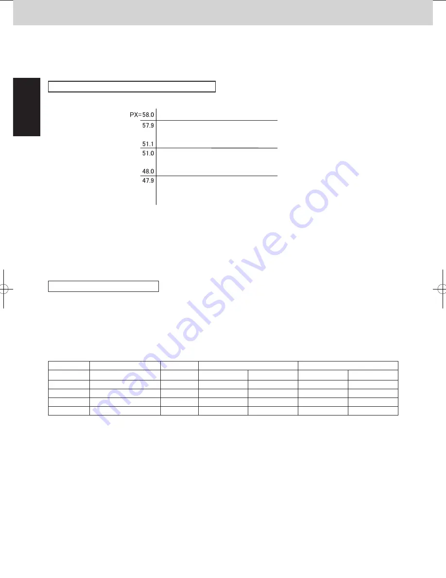
Condensation temperature area at heating operation
Limit pressure adjustment function
Compressor capacity can increase
Compressor capacity holds
Thermostat OFF
Compressor capacity decreases
Tc_tgt_max.
Tc_tgt_min.
deg
B area
A area
C area
*PX is usually fixed to 58deg. If the high pressure goes up rapidly after the compressor starts, the system
experiences urgent stop. The next time the system will start with lower PX.
*In the B area, the compressor capacity changes depending on the refrigerant condition.
*When the system operates in a minimum capacity, the system will continue operating for at least 6 minutes if the
condensation temperature area is C area.
*The condensation temperature is not adjusted when there are one or more indoor units that select the test run.
1
- 9
2WAY SYSTEM
Control Functions-Outdoor Unit
1
3. Compressor Control
3-7. Protection control
3-7-1. Compressor discharge temperature protection
Discharge temp.
The compressor capacity is controlled according to the table below.
3-7-2. Abnormal low pressure protection
The compressor capacity is controlled according to the table below.
*Discharge temperature that is used for this control is the highest temperature among all compressors.
106 deg
104 deg
103 deg
101 deg
Capacity goes down 2.0 HP
Capacity goes down 1.0 HP
Capacity goes down 0.5 HP
Compressor capacity cannot increase
Compressor capacity can increase
Compressor
capacity
decreases
105 deg
Stop If this temperature is detected at regular intervals, alarm appears.
Low pressure
0.25 MPa
0.17 MPa
Capacity goes up slowly
Capacity cannot increase
Capacity goes down
0.20 MPa
No restriction
3-7-3. Overcurrent protection of compressor
Current limitation of compressor is shown in the table below. This limitation is to protect the compressor, so that
the current of the power cable connected with the compressor is limited.
* For the inverter compressor, this is the secondary current from HIC board.
Inverter compressor
Limit current 2
Secondary
current
Max. current 2 H
unit : Amp.
10HP
21.8
19.3
18.3
8HP
19.6
17.1
16.1
12HP
17.6
15.1
14.1
14HP
21.0
18.5
17.5
16HP
22.5
20.0
19.0
18HP
21.0
18.5
17.5
20HP
21.0
18.5
17.5
Max. current 2 L
Constant speed compressor
Limit current
unit : Amp.
10HP
8HP
12HP
14.9
14HP
12.4
16HP
14.9
18HP
12.4
20HP
14.9
Limit current 2
Max. current 2 L
Stop
If this current is detected at regular intervals, alarm appears.
Frequency of inverter compressor goes down.
Frequency of inverter compressor can increase.
Frequency of inverter compressor cannot increase.
Max. current 2 H
Setting No.
Limited pressure
PX (°C)
Cooling mode
Heating mode
Tc_tgt_min
Tc_tgt_max
Tc_tgt_min
Tc_tgt_max
0
3.3MPa
52.5
47.0
49.0
47.0
48.0
1
No use
-
-
-
-
-
2
3.8MPa
58.0
53.0
55.0
48.0
51.0
3
No use
-
-
-
-
-
SM830204-05_2WAY SYS.indb 8
2015/01/21 16:59:59
Summary of Contents for U-20ME1E81
Page 54: ... MEMO 1 46 ...
Page 102: ... MEMO 3 36 ...
Page 116: ... MEMO 4 14 ...
Page 177: ...201502 ...


