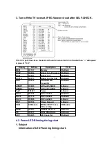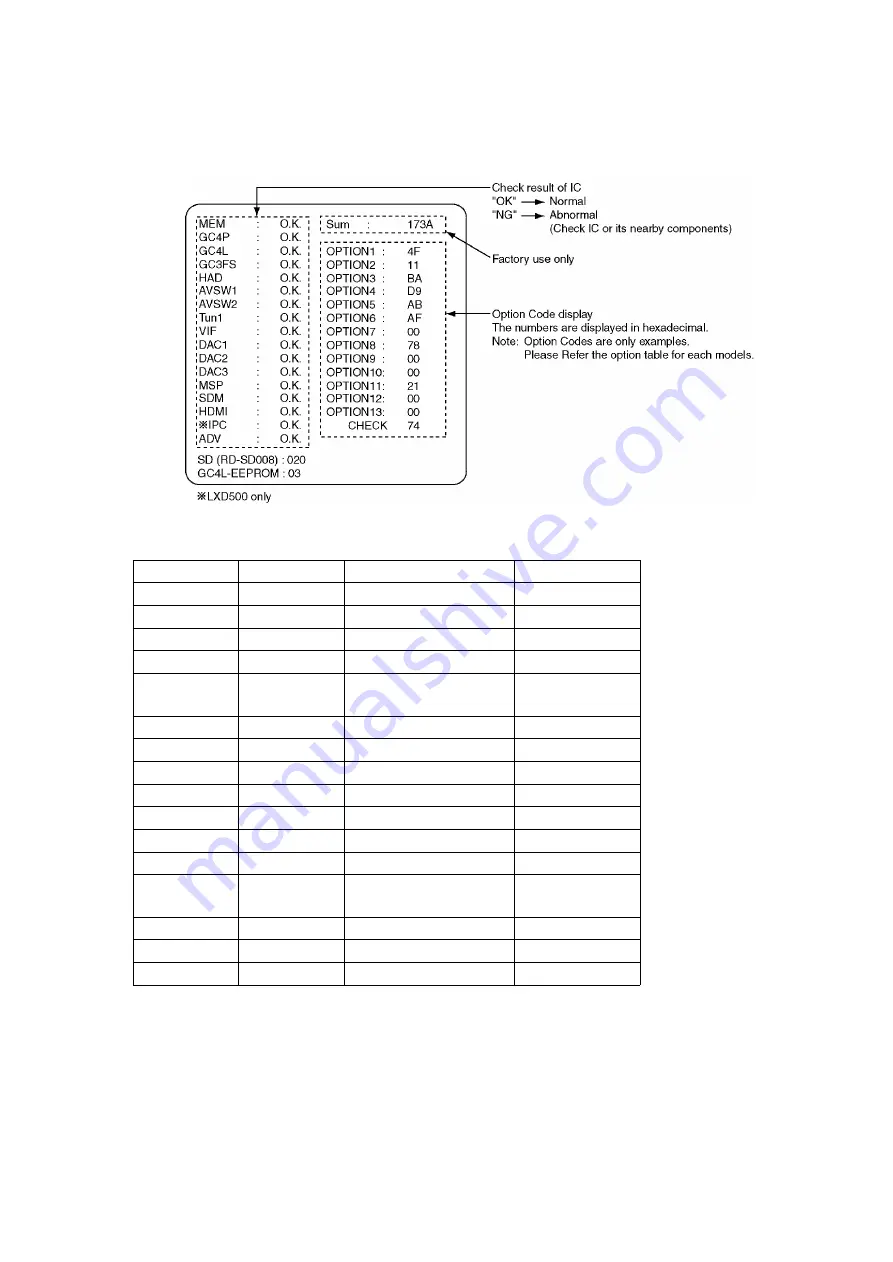
3. Turn off the TV to reset JPEG Viewer circuit after SELF-CHECK.
If the CCU ports have been checked and found to be incorrect or not located then “--” will appear
in place of “O.K.”.
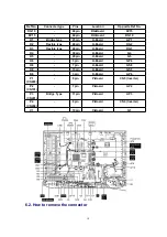
Display
Ref. No.
Description
P.C.B.
MEM
IC1107
Memory
DG-Board
GC4P
IC4054
Global Core Processor DG-Board
GC4L
IC4057
Global Core
DG-Board
GC3FS
IC4013
Global Core for Sub
DG-Board
HAD
IC4012
OSD RGB A/D
Converter
DG-Board
AVSW1
IC3005
AV Switch VIDEO
H-Board
AVSW2
IC2105
AV Switch AUDIO
H-Board
Tun1
TU3201
Tuner
H-Board
DAC1
IC1106
DAC control 1
DG-Board
DAC2
IC1116
DAC control 2
DG-Board
DAC3
IC3006
DAC control 3
H-Board
MSP
IC2106
Stereo Decoder
H-Board
SDM
SD-Module
MPEG4/PHOTO view,
SD recording
SD-Module
HDMI
IC5003
HDMI I/F Receiver
DV-Board
IPC
IC8013
HDSL PEAKS Lite
XV-Board
ADV
IC4005
A/D Converter
DG-Board
4.2. Power LED Blinking timing chart
1. Subject
Information of LED Flashing timing chart.
7
Summary of Contents for TX-26LX500F
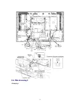
Page 12: ...6 4 Wire dressing 2 Clamping 12 ...
Page 24: ...24 ...
Page 25: ...8 3 Option Description 25 ...
Page 26: ...26 ...
Page 32: ...13 2 Front Chassis Layout 13 3 Cabinet Ass y Layout 32 ...
Page 33: ...13 4 Packing 33 ...
Page 58: ...IC2108 C0EBF0000354 IC 1 58 ...
Page 63: ...L8501 ELJNA2R7JB INDUCTION COIL 1 63 ...
Page 105: ...IC1104 C2CBYF000032 IC 1 105 ...
Page 107: ...IC5015 C0CBCAD00016 IC 1 107 ...
Page 111: ...Q1119 2SA207700L TRANSISTOR 1 111 ...
Page 162: ...11 Schematic Diagram 11 1 Schematic Diagram Notes 35 ...
Page 163: ...11 Schematic Diagram 11 1 Schematic Diagram Notes 35 ...


