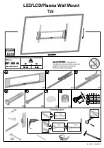
PLAYBACK PHASE ADJUSTMENT
S/W PULSE TEST PIN
PATH ADJ. JIG
TEST POINTS
VIDEO OUT
MAIN CIRCUIT BOARD
MEASURING EQUIPMENT
OSCILLOSCOPE
ADJUSTMENT
VR595 (PG SHIFTER)
MAIN CIRCUIT BOARD
The Phase generator (PG) shifter decides the VIDEO HEAD switching point when a TAPE is played back. In case the Phase
generator (PG) shifter is not correctly tuned, HEAD switching noise or vertical jitter may occur.
1)
Connect the PATH ADJ. JIG to PTO1 of the MAIN CIRCUIT BOARD.
2)
Play the ALIGNMENT TAPE (COLOUR BAR SIGNAL OR MONOSCOPE SIGNAL).
3)
Connect the channel-1 scope probe to the S/W PULSE TEST PIN of the PATH ADJ. JIG.
4)
Connect the channel-2 scope probe (1V/div.) to the VIDEO OUT of the MAIN CIRCUIT BOARD.
5)
Play back the ALIGNMENT TAPE.
6)
Adjust the PG volume for time interval of 6,5Hz±0,5Hz between switching pulse and V-sync signal.
29
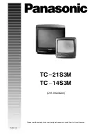
Playback phase adjustment
Fig.47.
SWITCHING
SW. PULSE
VIDEO OUTPUT
V.SYNC
Summary of Contents for TX-21GV1
Page 34: ...cp421vbl sch 1 Wed May 19 17 22 44 1999 VIDEO BLOCK DIAGRAM ...
Page 35: ...cp421abl sch 1 Wed May 19 17 19 52 1999 AUDIO BLOCK DIAGRAM ...
Page 36: ...cp421pbl1 sch 1 Wed May 19 17 21 31 1999 POWER BLOCK DIAGRAM ...
Page 48: ...39 6 3 EXPLODED VIEW OF F L ASS Y 3 576 2 7 21 9 5 ...
Page 50: ......
Page 51: ...SCHEMATIC DIAGRAMS FOR MODELS ZEICHENERKLÄRUNG FÜR MODELL TX 21GV1C TX 14GV1C ...
Page 52: ......
Page 53: ......