18
7 Disassembly and Assembly Instructions
Caution:
Exchange printed circuit board after confirm parts number.
7.1.
Remove the Rear cover
1. See Service Hint (Section 3)
7.2.
Remove the Fan unit
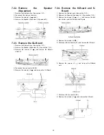
1. Unlock the cable clampers to free the cable.
2. Remove the screws (
×
3 ).
3. Remove the relay connectors and remove the Fan unit.
4. Remove the screw (
×
1
) on the back side.
5. Remove the Fan.
7.3.
Remove the PB-Board
1. Unlock the cable clampers to free the cable.
2. Remove the screws (
×
2 ).
3. Remove a short-jumper connectors (PB31 and PB32)
and re-use for new PB-Board.
4. Disconnect the connectors (PB30, PB33, PB34, PB35,
PB36 and PB37)
5. Remove the PB-Board.
7.4.
Remove the P(AC)-Board
Caution:
To remove P.C.B. wait 1 minute after power was off for dis-
charge from electrolysis capacitors.
1. Unlock the cable clampers to free the cable.
2. Disconnect the connectors (P9, P51, P53 and P55).
3. Remove the screws (
×
6
) and remove the P(AC)-
Board.
Parts name & Description
Parts No.
CIRCUIT BOARD A
TNPH0768S
CIRCUIT BOARD D
TNPA4439BKS
CIRCUIT BOARD SC
TXNSC1BJUC
CIRCUIT BOARD SS
TXNSS1BJUC
Summary of Contents for TH46PZ850UA - 46" PLASMA TV
Page 16: ...16 6 4 No Picture ...
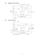
Page 29: ...29 8 1 4 Adjustment Volume Location 8 1 5 Test Point Location ...
Page 31: ...31 ...
Page 32: ...32 ...
Page 40: ...40 10 3 Wiring 2 ...
Page 41: ...41 10 4 Wiring 3 ...
Page 42: ...42 10 5 Wiring 4 10 6 Wiring 5 ...
Page 43: ...43 11 Schematic Diagram 11 1 Schematic Diagram Note ...
Page 108: ...108 ...
Page 110: ...110 13 1 2 Fan part location ...
Page 111: ...111 13 1 3 Accessories ...
Page 112: ...112 13 1 4 Mechanical Replacement Parts List ...
Page 116: ...116 13 2 Electrical Replacement Parts List 13 2 1 Replacement Parts List Notes ...


