1
Applicable signals
6
2
Safety Precautions
6
2.1.
General Guidelines
6
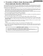
3
Prevention of Electro Static Discharge (ESD) to
Electrostatically Sensitive (ES) Devices
7
4
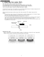
About lead free solder (PbF)
8
5
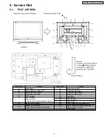
Service Hint
9
5.1.
TH-37, 42PX50U
9
5.2.
TH-50PX50U
10
6
Plasma panel replacement method
11
6.1.
Remove the Back cover.
11
6.2.
Remove the P-Board.
11
6.3.
Remove the PB-Board
11
6.4.
Remove the D-Board
11
6.5.
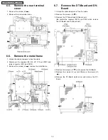
Remove the rear terminal cover
12
6.6.
Remove the metal frame
12
6.7.
Remove the DT-Board and DV-Board
12
6.8.
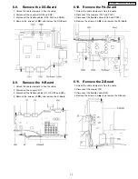
Remove the DG-Board
13
6.9.
Remove the H-Board
13
6.10. Remove the PA-Board
13
6.11. Remove the Z-Board
13
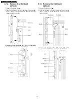
6.12. Remove the SU-Board(37inch)
14
6.13. Remove the SU-Board(42inch)
14
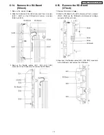
6.14. Remove the SU-Board(50inch)
15
6.15. Remove the SD-Board(37inch)
15
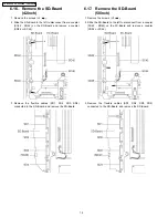
6.16. Remove the SD-Board(42inch)
16
6.17. Remove the SD-Board(50inch)
16
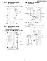
6.18. Remove the SC-Board(37, 42inch)
17
6.19. Remove the SC-Board(50inch)
17
6.20. Remove the SS2-Board(42, 50inch)
17
6.21. Remove the SS3-Board(42, 50inch)
17
6.22. Remove the SS-Board(37, 42inch)
18
6.23. Remove the SS-Board(50inch)
18
6.24. Remove the Fan
18
6.25. Remove the C1-Board(37, 42inch)
19
6.26. Remove the C2-Board(37, 42inch)
19
6.27. Remove the C1-Board(50inch)
19
6.28. Remove the C2-Board(50inch)
19
6.29. Remove the C3-Board(50inch)
20
6.30. Remove the Speaker L, R
20
6.31. Remove the stand brackets.
20
6.32. Remove the C3-Board(37, 42inch)
20
6.33. Remove the C4-Board(37, 42inch)
21
6.34. Remove the C4-Board(50inch)
21
6.35. Remove the C5-Board(50inch)
21
6.36. Remove the C6-Board(50inch)
21
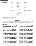
Humidity : 20 % - 80 % (non-condensing)
Connection Terminals
AV INPUT 1- 2
VIDEO
1.0 Vp-p (75
W
)
(Phono Jack Type)
S-VIDEO
Y : 1.0 Vp-p (75
W
), C : 0.286 Vp-p (75
W
)
(Mini DIN 4-pin)
AUDIO L-R
0.5 Vrms
(Phono Jack Type × 2)
AV PROG. OUT
VIDEO
1.0 Vp-p (75
W
)
(Phono Jack Type)
AUDIO L-R
0.5 Vrms
(Phono Jack Type × 2)
COMPONENT VIDEO
Y
1.0 Vp-p (including synchronization)
INPUT1-2
PB / PR
± 0.35 Vp-p
AUDIO L-R
0.5 Vrms
(Phono Jack Type × 2)
HDMI
HDMI type A Connector
AUDIO L-R
0.5 Vrms
(Phono Jack Type × 2)
DIGITAL AUDIO OUT
PCM / Dolby Digital, Fiber Optic
Note:
Design and Specifications are subject change without notice.
Weight and Dimensions shown are approximate.
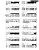
CONTENTS
Page
Page
2
TH-37PX50U / TH-42PX50U / TH-50PX50U
Summary of Contents for TH37PX50U - 37" HD PLASMA TV
Page 24: ...7 Location of Lead Wiring 7 1 Lead of Wiring 1 TH 37PX50U 24 TH 37PX50U TH 42PX50U TH 50PX50U...
Page 25: ...7 2 Lead of Wiring 2 TH 37PX50U 25 TH 37PX50U TH 42PX50U TH 50PX50U...
Page 26: ...7 3 Lead of Wiring 3 TH 42PX50U 26 TH 37PX50U TH 42PX50U TH 50PX50U...
Page 27: ...7 4 Lead of Wiring 4 TH 42PX50U 27 TH 37PX50U TH 42PX50U TH 50PX50U...
Page 28: ...7 5 Lead of Wiring 5 TH 50PX50U 28 TH 37PX50U TH 42PX50U TH 50PX50U...
Page 29: ...7 6 Lead of Wiring 6 TH 50PX50U 29 TH 37PX50U TH 42PX50U TH 50PX50U...
Page 30: ...7 7 Lead of Wiring 7 30 TH 37PX50U TH 42PX50U TH 50PX50U...
Page 31: ...7 8 Lead of Wiring 8 TH 37PX50U 31 TH 37PX50U TH 42PX50U TH 50PX50U...
Page 32: ...7 9 Lead of Wiring 9 TH 42PX50U 32 TH 37PX50U TH 42PX50U TH 50PX50U...
Page 33: ...7 10 Lead of Wiring 10 TH 50PX50U 33 TH 37PX50U TH 42PX50U TH 50PX50U...
Page 37: ...8 4 No Picture 37 TH 37PX50U TH 42PX50U TH 50PX50U...
Page 40: ...9 4 Option 40 TH 37PX50U TH 42PX50U TH 50PX50U...
Page 44: ...10 4 Adjustment Volume Location 44 TH 37PX50U TH 42PX50U TH 50PX50U...
Page 45: ...10 5 Test Point Location 45 TH 37PX50U TH 42PX50U TH 50PX50U...
Page 108: ...TH 37PX50U TH 42PX50U TH 50PX50U 108...
Page 228: ...14 2 Pcaking Exploded Views 1 228 TH 37PX50U TH 42PX50U TH 50PX50U...
Page 229: ...14 3 Pcaking Exploded Views 2 229 TH 37PX50U TH 42PX50U TH 50PX50U...
Page 230: ...14 4 Pcaking Exploded Views 3 230 TH 37PX50U TH 42PX50U TH 50PX50U...


