background image

19

MULTI PIP

Transparent Function and Insertion Function:

Two functions are available for blend PIP: the transparent function and the insertion function. Set these functions with 
“Transparency” or “Insert” in “MULTI PIP Setup”. (see page 43)

Transparent Function:

Data such as text are displayed transparently on the 

background image.

Insertion Function:

The sub screen image is divided into transparent and non-

transparent areas, and only the non-transparent areas are 

inserted and displayed on the background image.

Note:

Be aware that if you put the display in a public place for commercial purposes or a public showing and then use the blend PIP 

function to make a composite screen display, you may be violating the copyright under copyright law. It is prohibited to show or 

alter the copyrighted materials of other people for commercial purposes without the prior permission of the copyright holder.

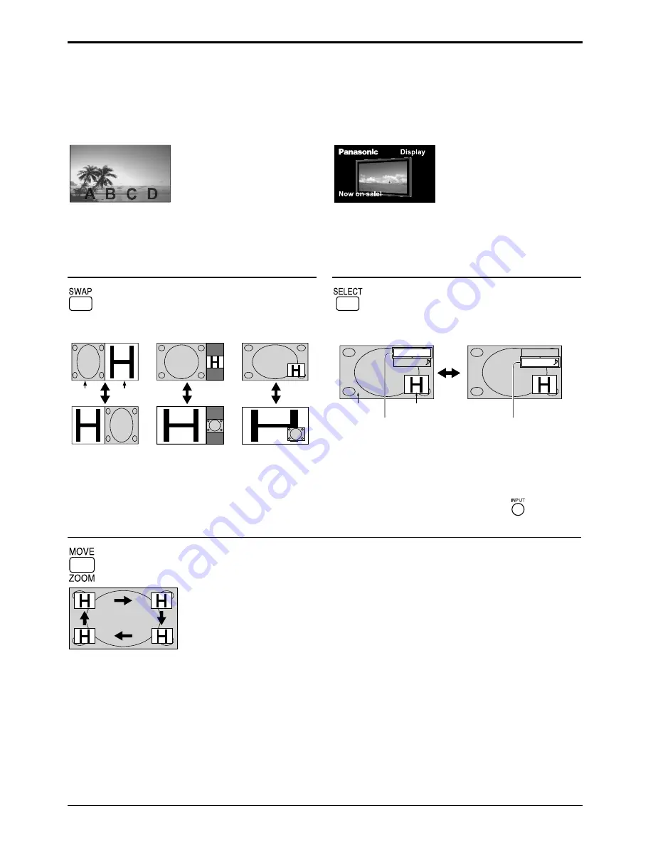
Swapping Screens

Selecting the Target Screen for Operations

  Each time this button is pressed, the main screen 

and sub screen are swapped.

  Each time this button is pressed, the target screen 

for operations changes.

Two screens

(P and P)

Main 

screen

Sub 

screen

Two screens

(P out P)

Two screens

(P in P)

PC

INPUT1

PC

INPUT1

Main screen

Sub screen

Main screen input mode

Sub screen input mode

Operations on the 

main screen

Operations on the 

sub screen

Notes:

• When operations are performed for the sub screen, the 

sub screen audio is played.

• If no operations are performed, the operation target 

returns to the main screen after about 5 seconds. You 
can also return to main screen operations by operating 
the remote control buttons (except for 

).

Selecting the Sub Screen Position (During P in P Display)

 Each time this button is pressed, the sub screen position changes.


Note:

Some sub screen positions may hide the display 
of the menu screen.

Notes:

•  Do not use the two-screen display for a long time. It will cause a permanent image retention to remain on the screen.

•  If “INPUT lock” in Options menu is set to other than “Off”, MULTI PIP function isn’t available.

•  Sound output is from the picture which is selected in Audio OUT (PIP) (see page 31).

•  In two-screen display, the same input mode cannot be selected for the main picture and sub picture.

•  The main picture and sub picture are processed by different circuits, resulting in a slight difference in the clarity of 

the pictures. There may also be a difference in the picture quality of the sub picture depending on the type of signals 

displayed on the main picture and depending on the two-screen display mode.

•  Due to the small dimensions of the sub pictures, these sub pictures cannot be shown in detail.

•  Computer screen picture is displayed in a simpli

fi

 ed format, and it may not be possible to discern details on them satisfactorily.

•  Following combinations of two analog signals cannot be displayed simultaneously;

  Component - Component, Component - PC (RGB), PC (RGB) - Component, PC (RGB) - PC (RGB)

•  2k1k signals that are received with the Dual Link HD-SDI Terminal Board (TY-FB11DHD) cannot be displayed in two-screen display.

Summary of Contents for TH-65PF12EK

Page 1: ...rating Instructions High Definition Plasma Display TH 58PF12EK TH 65PF12EK Please read these instructions before operating your set and retain them for future reference English The illustration shown...

Page 2: ...8 Customizing the Input labels 39 Selecting the On Screen Menu Language 39 Display orientation 40 Setup for MULTI DISPLAY 41 How to Setup MULTI DISPLAY 41 ID Remote Control Function 42 MULTI PIP Setup...

Page 3: ...noise to appear To avoid the possibility of harm to this appliance keep it away from sources of strong electromagnetic fields IMPORTANT THE MOULDED PLUG IMPORTANT THE MOULDED PLUG FOR YOUR SAFETY PLE...

Page 4: ...Transporting the unit with its display panel facing upright or downward may cause damage to the internal circuitry Speakers TY SP58P10WK for TH 58PF12EK TY SP65P11WK for TH 65PF12EK Pedestal TY ST58 K...

Page 5: ...at provided with this unit Doing so may cause fire or electric shocks Securely insert the power supply plug as far as it will go If the plug is not fully inserted heat may be generated which could cau...

Page 6: ...from direct or reflected light from your Plasma Display Cleaning and maintenance The front of the display panel has been specially treated Wipe the panel surface gently using only a cleaning cloth or...

Page 7: ...fe Precaution on battery use Incorrect installation can cause battery leakage and corrosion that will damage the remote control transmitter Disposal of batteries should be in an environment friendly m...

Page 8: ...pment Cable fixing band Secure any excess cables with band as required Note One fixing band is supplied with this unit In case of securing cables at two positions please purchase it separately Note Ma...

Page 9: ...o need to use an adapter for computers with DOS V compatible Mini D sub 15P terminal The computer shown in the illustration is for example purposes only Additional equipment and cables shown are not s...

Page 10: ...unit before sending the next command If an incorrect command is sent by mistake this unit will send an ER401 command back to the computer SL1A SL1B SL2A and SL2B of Command IMS are available only when...

Page 11: ...er plugs shown are not supplied with this set Refer to page 49 for applicable input signal Use the DVI D cable complying with the DVI standard Image deterioration may occur depending on the length or...

Page 12: ...y pressing the switch on the unit when the Plasma Display is on or in standby mode Note During operation of the power management function the power indicator turns orange in the power off state Connec...

Page 13: ...ching on the unit Following screen will be displayed when the unit is turned on for the first time Select the items with the remote control Unit buttons are invalid OSD Language PRESENT TIME Setup Dis...

Page 14: ...ed for the main picture and sub picture Image retention image lag may occur on the plasma display panel when a still picture is kept on the panel for an extended period The function that darkens the s...

Page 15: ...ge 21 Enter Aspect button see page 17 21 Remote control sensor Main Power On Off Switch Power Indicator The Power Indicator will light Power OFF Indicator not illuminated The unit will still consume s...

Page 16: ...put signal Ex INPUT1A INPUT1B MULTI Window buttons see page 18 Digital Zoom see page 20 AUTO SETUP button Automatically adjusts the position size of the screen see page 23 SET UP button see page 21 SO...

Page 17: ...layed in 4 3 mode for an extended period as this can cause a permanent image retention to remain on the Plasma Display Panel Panasonic Auto The display will automatically become enlarged depending on...

Page 18: ...hen Display Mode in MULTI PIP Setup is changed see page 43 During PIP During Advanced PIP One screen Advanced PIP Main screen Sub screen 1 8 2 7 3 6 4 5 One screen Two screens P and P Sub screen input...

Page 19: ...is played If no operations are performed the operation target returns to the main screen after about 5 seconds You can also return to main screen operations by operating the remote control buttons exc...

Page 20: ...Return to normal display quit Digital Zoom Press to exit from the Digital Zoom The cursor will move Notes When power goes OFF including Off Timer operation Digital Zoom terminates The Digital Zoom fu...

Page 21: ...Normal Viewing Picture Sound Pos Size Setup 2 Select the item 25 0 0 0 5 Picture Normal Normalise Normal Brightness Sharpness Picture Mode Colour Contrast Hue Colour Management Advanced settings Memor...

Page 22: ...enu setting see page 31 see page 32 51 3D Y C Filter NTSC Colour system Signal Cinema reality Panasonic Auto 4 3 AV Noise reduction On Auto Off 4 3 Off see page 47 50 Screensaver Start Function Scroll...

Page 23: ...t is not memorized When exiting the mode the screen will return to a former adjustment 4 During Video S Video Digital SDI and HDMI input signal During Component RGB and PC input signal Auto Setup H Po...

Page 24: ...162 MHz or higher Dot Clock and Clock Phase cannot be made When digital RGB signal input Dot Clock and Clock Phase cannot be made Auto Setup may not work when a cropped or dark image is input In such...

Page 25: ...On 1 1 Pixel Mode 2k1k For 2k1k signals When the input signal is a 2k1k signal 2048 1080 24p 2048 1080 24sF the display size is adjusted as follows Off On Left On Center On Right Note 2k1k signals ca...

Page 26: ...u setting Picture Adjustments Normal Cool Warm Press or button to switch between modes Normal Monitor Dynamic Cinema Normal For viewing in standard evening lighting environments This menu selects the...

Page 27: ...bright sections using the W B High R W B High G and W B High B settings 2 Adjust the white balance of the dark sections using the W B Low R W B Low G and W B Low B settings 3 Repeat steps 1 and 2 to...

Page 28: ...s Picture Mode Colour Contrast Hue Colour Management Advanced settings White balance 25 0 0 0 5 Picture Normal Normal Normal Off Normalise Brightness Sharpness Picture Mode Colour Contrast Hue Colour...

Page 29: ...ering profile names Profile names can be up to 16 characters To enter text select characters in the on screen keyboard Edit the default profile name in the text box as desired Memory name input Ok A M...

Page 30: ...t the profile to delete To delete all profiles select All delete Memory delete 2 3 MEMORY2 MEMORY3 All delete 4 MEMORY4 MEMORY1 1 1 select 2 set 4 Select Ok Memory delete Cancel Delete the MEMORY1 dat...

Page 31: ...dio channel Sound Out On Off On Enables audio output Off Disables audio output Level Meter Off 1 8ch 9 16ch Sets audio channels to show in the audio level meter 8 channels are displayed in the audio l...

Page 32: ...orward button Back Notes Pressing or button once changes PRESENT TIME 1 minute Pressing or button continuously changes PRESENT TIME by 15 minutes Press to select Set Press to store PRESENT TIME Setup...

Page 33: ...Screensaver The menu screen will disappear and the Screensaver will be activated To stop the Screensaver under On press the R button or any buttons on the main unit Note When the display is turned off...

Page 34: ...e is On or Off Press to select Start Time Finish Time when Time Designation is selected Press to select Periodic Time Operating Time when Interval is selected Press to select Screensaver duration when...

Page 35: ...applicable to the non picture area Off Darken both ends Low Make it dark gray Mid Make it gray High Make it light gray Notes To reduce the occurrence of image retention set the Side panel to High The...

Page 36: ...ettings Reset Extended life settings 1 select 2 access 2 Select the input to apply the settings Apply to current input Apply to all inputs Extended life settings 1 select 2 set 3 Select Yes Apply to c...

Page 37: ...settings 1 select 2 adjust When a menu is locked it is grayed out and cannot be set Picture Mode and Contrast will no longer be able to set in the Picture menu and they are labeled with icon to indic...

Page 38: ...tes under the following conditions to turn the power on or off automatically When no pictures HD VD sync signals are detected for 30 or so seconds during PC signal input Power is turned off standby th...

Page 39: ...al Terminal Board connected to Slot1 Slot2 and Slot3 the Input label will depend on each Optional Terminal Board Addition sign A B Selected Input Composite S VIDEO When BNC Dual Video Terminal Board T...

Page 40: ...the Setup menu Press to select Display orientation Press to select Landscape or Portrait Press to exit from adjust mode 1 2 3 Notes Turn up the power switch for the upward direction when you set Displ...

Page 41: ...may be displayed across all screens For this mode of operation each plasma display has to be set up with a Display number to determine its location Example group of 16 4 4 group of 4 2 2 group of 9 3...

Page 42: ...Press one of for the tens digit setting Press one of for the units digit setting 4 Notes The numbers in 2 3 and 4 should be set up quickly Adjustable ID number range is 0 99 If a number button is pre...

Page 43: ...sert sub screen Insert level Background image main screen Two picture Insertion Only the areas on the overlay image that are brighter than the Insert level are displayed on the background image 10 1 N...

Page 44: ...ll be enlarged 3 times and rotated 90 degree Set up for Portrait Press to display the Setup menu Press to select the Portrait Setup Press to display the Portrait Setup menu Press to select the Portrai...

Page 45: ...ngArea is set at 16 9 and cannot be changed HD signal 1125 1080 60i 50i 60p 50p 24p 25p 30p 24sF 750 720 60p 50p 1250 1080 50i When Viewing Area is 16 9 the aspect mode is set to 16 9 5 Viewing Area S...

Page 46: ...nals RGB 1 2 Press to display the Setup menu Press to select the Component RGB in select Press to select the desired input signal Component RGB Press to exit from adjust mode Notes Selection may not b...

Page 47: ...at 1280 1024 60 Sync Signal H Freq V Freq kHz Hz 63 98 60 02 Signal Format 1280 1024 60 RGB Cinema reality Noise reduction XGA Mode Auto Off Off Auto 47 3D Y C Filter For NTSC AV images Select Signal...

Page 48: ...the colour system to match the input signal When selecting Auto the Colour system is automatically selected from NTSC PAL SECAM however M NTSC signal is not displayed properly depending on the attach...

Page 49: ...he following three NR Noise Reduction functions together P NR Mosquito NR Block NR Noise reduction Setup for Input Signals Sets the three NR functions separately Press to select Advanced Press to ente...

Page 50: ...nized signal of Composite Sync input which is input from the HD connector Sync Setup for Input Signals Press to select the Sync Press to adjust Displays the frequency and the type of the current input...

Page 51: ...function To obtain an IP address automatically using a DHCP server set this to On If DHCP server is not used set this to Off IP address IP address display and setting Enter an IP address if DHCP serv...

Page 52: ...d Aor B is displayed depending on the selected input signal Ex INPUT1A INPUT1B Initial VOL level Press button to adjust the volume when the unit is turned on Off On Off Sets normal volume On Sets your...

Page 53: ...ter plugging off and in again Normal Power returns in as the same state as before the power interruption Standby Power returns in standby mode Power Indicator red orange On Power returns in power On P...

Page 54: ...lying the power to the board with time delay according to the setting The power indicator lights up red first and it turns orange when the power starts being supplied to the board Clock Display Off No...

Page 55: ...can set 7 day timer programming by setting time and command Note Before setting Weekly Command Timer set PRESENT TIME Setup see page 32 Press to select Function Press to select On Note When Function...

Page 56: ...to select a command number 6 Press to select Time Command Press to set each item Time Set the time to execute a command program Pressing or button once changes Time 1 minute Pressing or button contin...

Page 57: ...sure the broadband router or hub supports 10BASE T 100BASE TX To connect a device using 100BASE TX use category 5 LAN cable Touching the LAN terminal with a statically charged hand body may cause dam...

Page 58: ...on mute 30 Shutter mode Off picture and audio mute deactivated 31 Shutter mode On picture and audio on mute AVMT Shutter control query Parameter 11 Picture Off picture on mute 21 Audio Off audio on mu...

Page 59: ...cur between image and audio depending on the type of input signal However this is not a malfunction Plasma Display panel Symptoms Check The screen darkens slightly whenbrightpictureswithminimal moveme...

Page 60: ...screen is slightly elongated 4 3 4 3 Pictures with a 4 3 aspect ratio are displayed with their original aspect ratio Side panels are displayed at the left and right edges of the screen 4 3 1 4 3 2 Th...

Page 61: ...8 60 Hz 48 36 60 00 65 0 65 0 32 1 024 768 70 Hz 56 48 70 07 75 0 33 1 024 768 75 Hz 60 02 75 03 78 75 34 1 024 768 85 Hz 68 68 85 00 94 5 35 1 066 600 60 Hz 37 64 59 94 53 0 53 0 36 1 152 864 60 Hz 5...

Page 62: ...e Picture in Picture 36 DWA POP Dual Picture mode Picture out Picture 37 DWA SWP Swap main picture and sub picture when PIP mode 38 DWA TWN Dual Picture mode Picture and Picture 39 IMS PC1 Input selec...

Page 63: ...Stereo mini jack M3 1 0 5 Vrms Compatible with HDCP 1 1 LAN RJ45 10BASE T 100BASE TX compatible with PJLink COMPONENT RGB IN Y G BNC PB B BNC PR R BNC Audio Input with sync 1 0 Vp p 75 0 7 Vp p 75 Ste...

Page 64: ...ish regulations are stated Copyright 1980 1986 1993 The Regents of the University of California All rights reserved Redistribution and use in source and binary forms with or without modification are p...

Reviews: