


24
TH-65PF11EK
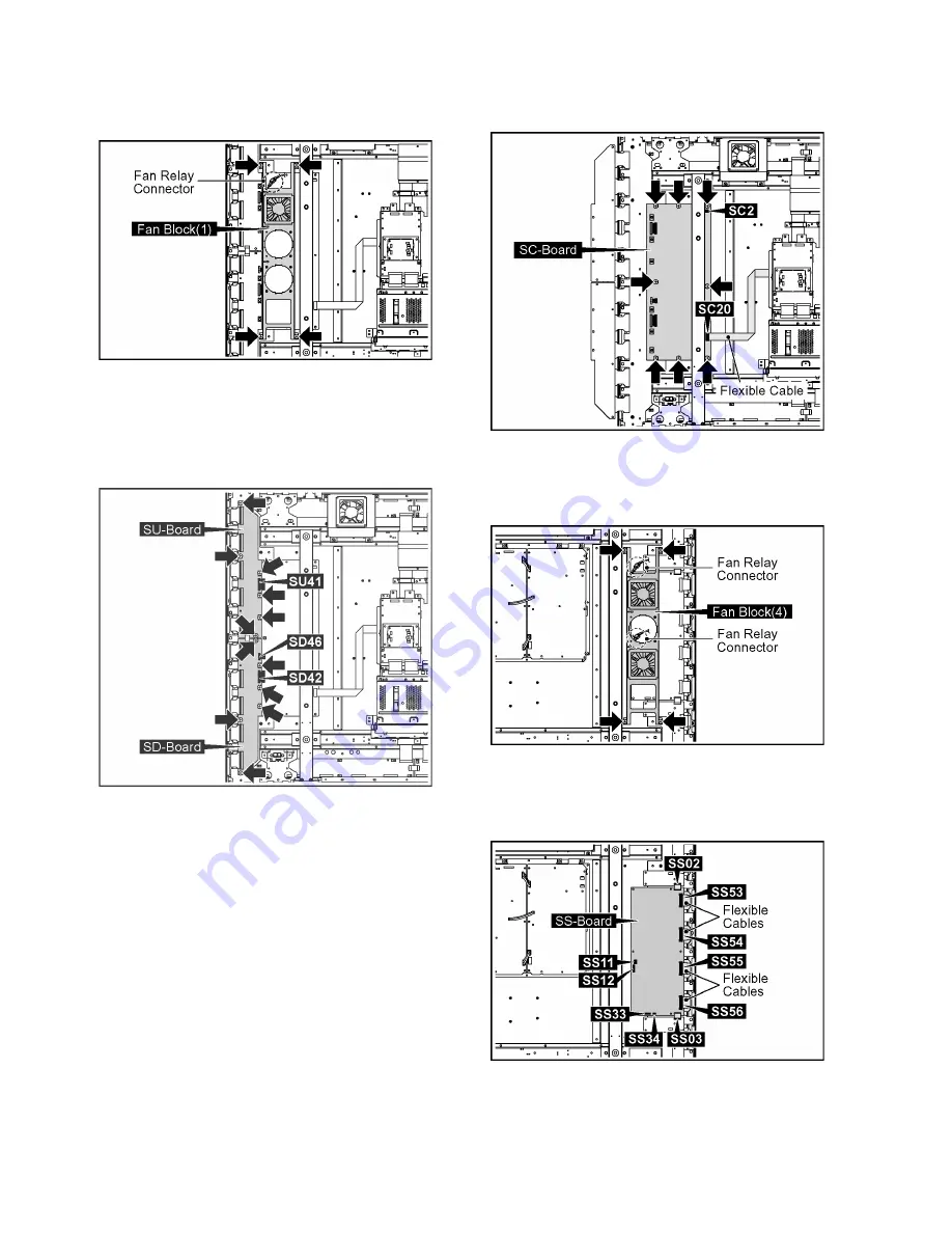
8.14. Removal of SC-Board
1. Disconnect the Fan Relay Connector.
2. Remove 4 screws and then remove the Fan Block (1).
3. Disconnect the connectors (SU41, SD42, SD46).
4. Remove 12 screws.
5. Turn over SU-Board and SD-Board to the left.
Note:
Do not damage the Flexible Cables of SU-Board and
SD-Board, and the parts on SC-Board.
6. Disconnect the connector (SC2).
7. Remove the flexible cable from the connector (SC20).
8. Remove 8 screws and then remove SC-Board.
8.15. Removal of SS-Board
1. Disconnect the Fan Relay Connector.
2. Remove 4 screws and then remove the Fan Block (4).
3. Disconnect the connectors (SS02, SS03, SS11, SS12,
SS33, SS34).
4. Remove the flexible cables from the connectors (SS53,
SS54, SS55, SS56).
Summary of Contents for TH-65PF11EK
Page 7: ...7 TH 65PF11EK 3 2 Applicable signals ...
Page 9: ...9 TH 65PF11EK 5 Operating Instructions ...
Page 14: ...14 TH 65PF11EK 6 2 IIC mode structure following items value is sample data ...
Page 35: ...35 TH 65PF11EK 9 1 4 Adjustment Volume Location 9 1 5 Test Point Location ...
Page 37: ...37 TH 65PF11EK ...
Page 39: ...39 TH 65PF11EK ...
Page 40: ...40 TH 65PF11EK ...
Page 50: ...TH 65PF11EK 50 ...
Page 51: ...51 TH 65PF11EK 11 Wiring Connection Diagram 11 1 Wiring 1 ...
Page 52: ...52 TH 65PF11EK 11 2 Wiring 2 ...
Page 53: ...53 TH 65PF11EK 11 3 Wiring 3 ...
Page 54: ...54 TH 65PF11EK ...
Page 55: ...TH 65PF11EK 55 12 Schematic Diagram 12 1 Schematic Diagram Notes ...
Page 185: ...Model No TH 65PF11EK Note ...
Page 186: ...Model No TH 65PF11EK Exploded View ...
Page 187: ...Model No TH 65PF11EK Cabinet part location ...
Page 188: ...Model No TH 65PF11EK Fan part location ...
Page 189: ...Model No TH 65PF11EK Flat cable ...
Page 190: ...Model No TH 65PF11EK Accessories ...
Page 191: ...Model No TH 65PF11EK Packing 1 ...
Page 192: ...Model No TH 65PF11EK Packing 2 ...


