background image

17

English

Basic Controls

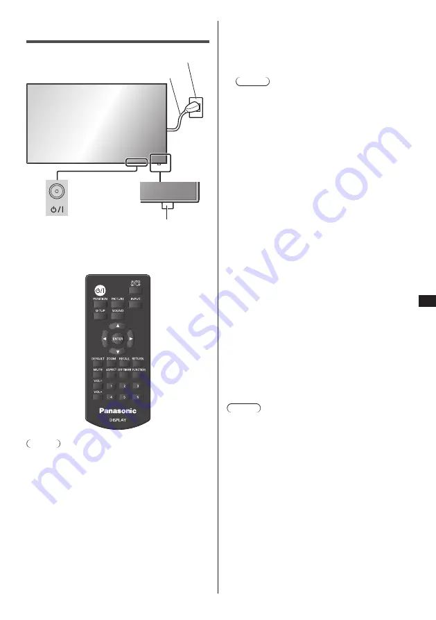
MUTE

Remote Control Sensor / 

Power Indicator

Main Power On / Off button
(Back of the unit)

AC socket outlet

AC cord (supplied)

Operate pointing the remote control directly at 

the unit’s Remote Control Sensor.

Note

● 

For normal use, pull out the remote control sensor 

from the edge side of the main unit by operating the 

lever on the rear panel. (see page 15)

● 

Do not put an obstacle between the remote control 

sensor of the main unit and the remote control.

● 

Operate the remote control in front of the remote 

control sensor or from the area where the sensor can 

be seen.

● 

When directly aiming the remote control at the remote 

control sensor of the main unit, the distance from 

the front of remote control sensor should be approx. 

7 m or less. Depending on the angle, the operation 

distance may be shorter.

● 

Do not subject the remote control sensor of the main 

unit to the direct sunlight or strong fluorescent light.

1

Connect the AC cord plug to the 

Display.

(see page 12)

2

Connect the plug to the socket outlet.

Note

● 

Main plug types vary between countries. The 

power plug shown at left may, therefore, not be the 

type fitted to your set.

● 

When disconnecting the AC cord, be absolutely 

sure to disconnect the AC cord plug at the socket 

outlet first.

● 

The settings may not be saved if the power plug is 

disconnected immediately after changing settings 

with on-screen menu. Disconnect the power plug 

after a enough period of time. Or, disconnect the 

power plug after turning the power off with the 

remote control, RS-232C control or LAN control.

3

Press the <Main Power On / Off 

button> on the unit to turn the set on: 

Power-On.

● 

Power Indicator: Green (Picture is displayed.)

● 

When the power of the unit is ON, remote control 

operation is possible.


To turn the power ON/OFF with the remote 

control

Press the <Standby (ON/OFF) button> to turn the 

Display on.

● 

Power Indicator: Green (Picture is displayed.)

Press the <Standby (ON/OFF) button> to turn the 

Display off.

● 

Power Indicator: Red (standby)

Press the <Main Power On / Off button> on the unit to 

turn the unit off, when the power of the unit is turned 

on or in standby mode.

Note

● 

During operation of the “Power management” 

function, the power indicator turns orange in the 

power off state.

● 

After the power plug is disconnected, the power 

indicator may remain lit for a while. This is not a 

malfunction.

Summary of Contents for TH-65EF1E

Page 1: ...12 Identifying Controls 15 Basic Controls 17 Specifications 19 Software License 21 Panasonic Professional Flat Panel Display Limited Warranty 22 LIMITED WARRANTY STATEMENT 23 Customer Service 24 Pleas...

Page 2: ...block any ventilation openings Install in accordance with the manufacturer s instructions 8 Do not install near any heat sources such as radiators heat registers stoves or other apparatus including a...

Page 3: ...pense FCC CAUTION To assure continued compliance follow the attached installation instructions and use only the provided power supply cord Any changes or modifications not expressly approved by Panaso...

Page 4: ...of Crestron Electronics Inc Crestron Connected is the trademark of Crestron Electronics Inc Even if no special notation has been made of company or product trademarks these trademarks have been fully...

Page 5: ...three pin mains plug for your safety and convenience A 10 amp fuse is fitted in this plug Shall the fuse need to be replaced please ensure that the replacement fuse has a rating of 10 amps and that i...

Page 6: ...ing the Display vertically When installing the Display vertically be sure that the Power Indicator comes to the downside Heat is generated and it may cause fire or damage to the Display Power indicato...

Page 7: ...from the wall outlet Picture noise may occur if you connect disconnect the cables connected to the input terminals you are currently not watching or if you turn the power of the video equipment on of...

Page 8: ...40 C 32 F to 104 F When using the unit at high altitudes 1 400 m 4 593 ft and higher and below 2 800 m 9 186 ft above sea level 0 C to 35 C 32 F to 95 F Do not install the unit where it is 2 800 m 9 1...

Page 9: ...uts strong radio wave near the installation location set up the Display at a location sufficiently far from the source of the radio wave Or wrap the LAN cable connected to the LAN terminal by using a...

Page 10: ...cord Approx 2 m TH 65EF1U 1JP155AF1U TH 65EF1E 2JP155AF1W 3JP155AF1W Attention Store small parts in an appropriate manner and keep them away from young children The part numbers of accessories are sub...

Page 11: ...nvironment friendly manner Observe the following precaution 1 Batteries shall always be replaced as a pair Always use new batteries when replacing the old set 2 Do not combine a used battery with a ne...

Page 12: ...ug at the socket outlet first The supplied AC cord is for this unit exclusive use Do not use this for other purposes Cable fixing Note 3 clampers are supplied with this unit Fix the cables at 3 locati...

Page 13: ...DVI D output 5 SERIAL IN SERIAL Input Terminal Control the Display by connecting to PC 6 LAN LAN Terminal Control the Display by connecting to Network 7 USB USB Terminal Connect the USB memory to use...

Page 14: ...ernal device to the system that is neither supplied with the device nor available as an option If the outer shape of the plug of a connection cable is large it may come in contact with the periphery s...

Page 15: ...with Power management function Orange Red Green When the power of the unit is OFF Main Power On Off button OFF No light Note Even if the display unit is turned off with the power indicator off some of...

Page 16: ...osition size of the screen 11 INPUT Switches input to display on the screen 12PICTURE 13SOUND 14RECALL Displays the current setting status of Input mode Aspect mode etc 15RETURN Used to return to the...

Page 17: ...tries The power plug shown at left may therefore not be the type fitted to your set When disconnecting the AC cord be absolutely sure to disconnect the AC cord plug at the socket outlet first The sett...

Page 18: ...ing menus OSD language Display orientation Power ON message The following message may be displayed when turning the unit power ON No activity power off Precautions No activity power off is enabled Whe...

Page 19: ...midity 20 80 no condensation Connection terminals HDMI 1 HDMI 2 TYPE A Connector 2 2 Audio signal Linear PCM sampling frequencies 48 kHz 44 1 kHz 32 kHz DVI D IN DVI D 24 Pin 1 Compliance with DVI Rev...

Page 20: ...range Approx 7 m 22 9 ft when operated directly in front of remote control sensor Mass Approx 63 2 22 oz including batteries Dimensions W H D 44 mm 105 mm 20 5 mm 1 74 4 14 0 81 1 Environmental temper...

Page 21: ...to any third party who contacts us at the contact information provided below for a charge no more than our cost of physically performing source code distribution a complete machine readable copy of th...

Page 22: ...e Company address indicated above Panasonic Solutions Company referred to as the Warrantor will repair this product and all included accessories with new or refurbished parts free of charge in the USA...

Page 23: ...ed portion of the original warranty coverage period Proof of product purchase is a condition of warranty service The owner must produce the product purchase receipt or other satisfactory evidence of d...

Page 24: ...English 24 Customer Service...

Page 25: ...on Disposal in other Countries outside the European Union These symbols are only valid in the European Union If you wish to discard these items please contact your local authorities or dealer and ask...

Reviews: