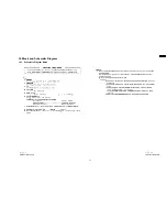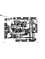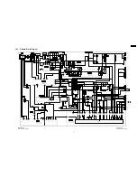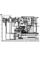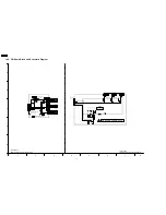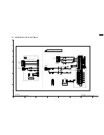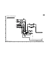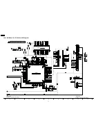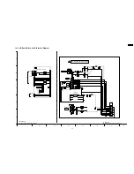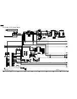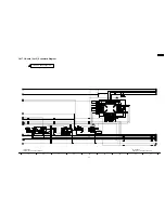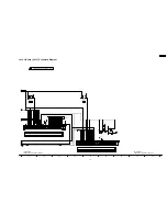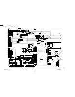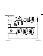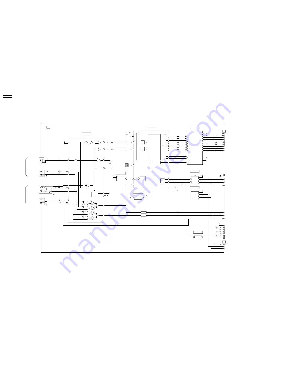
14.8. HU-Board Block Diagram
C
Y
L
R
L
R
1.8V
1.8V
3.3V
3.3V
3.3V
5V
5V_STB
5V_STB
9V
5V
3.3V
3.3V
9V
1
2
4
12
10
14
9
11
HU DUAL VIDEO TERMINAL(BNC/S)
B1
B2
5
A2
6
3
LEVEL CHANGE
A1
2
SDA
SCL
6
5
IC3309
CONFIG ROM
1
5
VOUT
VDD
IC3303
AVR 1.8V
43
45
40
36
Q3302,Q3306
29
V/Y
(+6db)
IN
V/CVB
(+6db)
Q3301,Q3305
C
C IN
68
6db
6db
6db
Y IN
1
1
VOUT
1
COUT
YOUT
1
V1
LV1
RV1
C2
Y2
S2
LV2
RV2
LOGIC
26
27
SCL
SDA
6db
0db
6db
0db
39
1
LOUT
41
1
ROUT
JK3301
VIDEO IN
JK3302
AUDIO IN
L
R
S-VIDEO IN
JK3304
JK3303
R
AUDIO IN
L
164
X3301
27MHz
HD VIDEO DECODER (10bit ADC)
IC3304
SDRAM
IC3305
16M bit
60
RESETX
VCC
VOUT
4
5
RESET
IC3302
96
95
93
94
92
91
90
89
105
106
84
83
MPU
I/F
SCL
SDATX
SCL
SDA
IC3306
3,3V
5V
4
31
12
27
7
28
10
6
11
8
14
ANALOG FR
ONT END(MUX/CLAM/A
GC)
DOUT(2)
SCL
B12
TXC+
TXC-
TO J12
SDA
H1
B25
B24
39
37
40
42
41
45
38
46
47
48
B11
B15
B9
B14
B6
B8
B3
B5
B2
TX3+
TX3-
TX2+
TX2-
TX1+
TX1-
TX0+
TX0-
B28
PLUG DETECT
B23
SRQ
H0
2
6
7
FACTORY
FOR
USE
SRQ
SCL
SDA
SCL(5V)
SDA(5V)
A26
L
R
A28
Q3304
Q3303
L(0dB)
R(0dB)
S2 DETECT
B36
A22
5V_STB
9V
A21
9V
B21
A19
5V
5V
3.3V
A17
B19
B17
3.3V
SDRAM
I/F
XIN
99
CLOCK GENE
DOUT(3)
DOUT(4)
DOUT(5)
DOUT(7)
DOUT(6)
DOUT(8)
DOUT(9)
G0
G1
G2
G5
G3
G4
G7
G6
TCLK+
TD+
TC+
TB+
TD-
TA+
TC-
TB-
TA-
TCLK-
IC3307
LVDS TX
TC4
CLK_IN
TC5
HD
VD
VD
HD
RCLK0
27MHz
VIDEO
SIGNAL
PROCCESSOR
Synchroni-
zation
Y/C Sepa
Chroma Demo
Noise Reduce
Picture
Adjust/
Enhancer
Flame TBC
OUTPUT I/F(FORMA
TTER/B
UFFER)
AV SW
IC3301
ADC
ADC
SCL(3.3V)
SDA(3.3V)
TD2
TD3
TB0
TA6
TB2
TB1
TB4
TB3
TH-50PH9UK
HU-Board Block Diagram
TH-50PH9UK
HU-Board Block Diagram
TH-50PH9UK
76
Summary of Contents for TH-50PH9UK
Page 4: ...1 Applicable signals 4 TH 50PH9UK ...
Page 20: ...7 Location of Lead Wiring 7 1 Location of Lead Wiring 1 20 TH 50PH9UK ...
Page 21: ...7 2 Location of Lead Wiring 2 21 TH 50PH9UK ...
Page 22: ...7 3 Location of Lead Wiring 3 7 4 Location of Lead Wiring 4 22 TH 50PH9UK ...
Page 25: ...8 4 Adjustment Volume Location 8 5 Test Point Location 25 TH 50PH9UK ...
Page 29: ...9 2 IIC mode structure following items value is sample data 29 TH 50PH9UK ...
Page 31: ...31 TH 50PH9UK ...
Page 33: ...33 TH 50PH9UK ...
Page 36: ...3 Remarks Above Fan function is operated while the fans are installed 36 TH 50PH9UK ...
Page 39: ...12 Option Setting 39 TH 50PH9UK ...
Page 69: ...14 Block and Schematic Diagram 14 1 Schematic Diagram Notes TH 50PH9UK 69 ...
Page 130: ...NOTE TH 50PH9UK 130 ...
Page 131: ...15 Parts Location 15 1 Exploded View 15 1 1 The main mechanical parts relation 131 TH 50PH9UK ...
Page 133: ...15 3 Cable relation 133 TH 50PH9UK ...
Page 134: ...15 4 Packing summary 134 TH 50PH9UK ...
Page 136: ...17 Replacement Parts List 17 1 Replacement Parts List Notes 136 TH 50PH9UK ...


