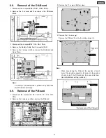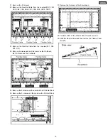
6.8. Removal of the DA-Board
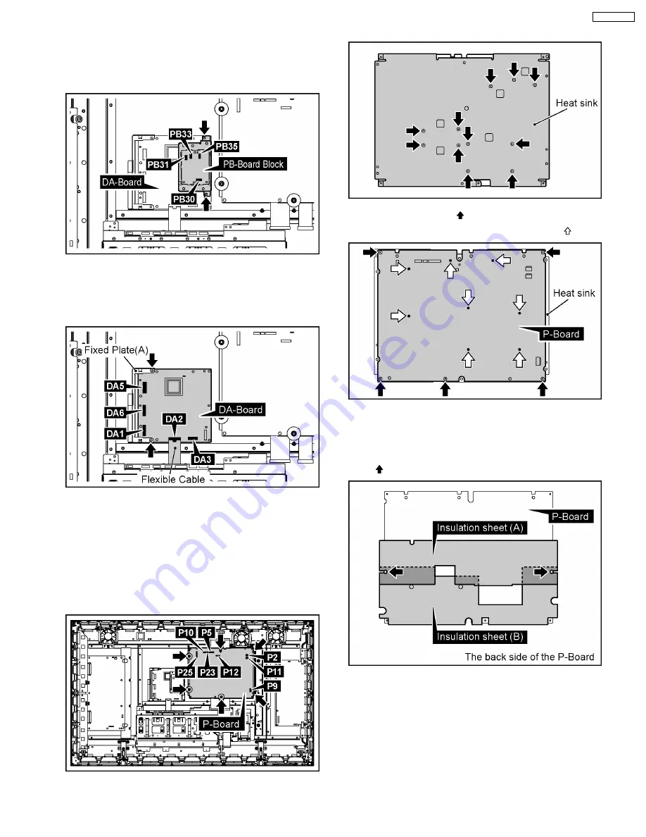
1. Disconnect the couplers(PB30, PB31, PB33, PB35).
2. Remove the 2 screws and then remove the PB-Board
Block.
3. Disconnect the couplers(DA1, DA3, DA5, DA6).
4. Remove the Flexible Cable from the coupler(DA2).
5. Remove the 2 screws and then remove the DA-Board and
Fixed Plate.
Note:
A re-setup of the destination is performed by MS mode
after DA-Board exchange.
6.9. Removal of the P-Board
1. Disconnect the couplers(P2, P5, P9, P10, P11, P12, P23,
P25).
2. Remove the 6 screws and then remove the P-Board.
3. Remove the 11 screws (Bottom view).
4. Remove the 5 screws ( ).
Remove the P-Board from the 8 molding props ( ).
Note:
·
When assembling the P-Board, the position of each
hole of the insulation sheets(A, B) are set to the position
of each hole of the P-Board and then assemble them.
( marks indicate setting positions.)
11
TH-50PH9UK
Summary of Contents for TH-50PH9UK
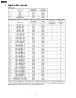
Page 4: ...1 Applicable signals 4 TH 50PH9UK ...
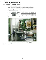
Page 20: ...7 Location of Lead Wiring 7 1 Location of Lead Wiring 1 20 TH 50PH9UK ...
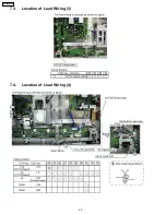
Page 21: ...7 2 Location of Lead Wiring 2 21 TH 50PH9UK ...
Page 22: ...7 3 Location of Lead Wiring 3 7 4 Location of Lead Wiring 4 22 TH 50PH9UK ...
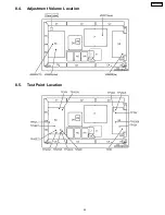
Page 25: ...8 4 Adjustment Volume Location 8 5 Test Point Location 25 TH 50PH9UK ...
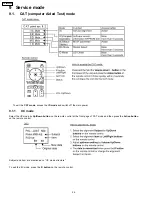
Page 29: ...9 2 IIC mode structure following items value is sample data 29 TH 50PH9UK ...
Page 31: ...31 TH 50PH9UK ...
Page 33: ...33 TH 50PH9UK ...
Page 36: ...3 Remarks Above Fan function is operated while the fans are installed 36 TH 50PH9UK ...
Page 39: ...12 Option Setting 39 TH 50PH9UK ...
Page 69: ...14 Block and Schematic Diagram 14 1 Schematic Diagram Notes TH 50PH9UK 69 ...
Page 130: ...NOTE TH 50PH9UK 130 ...
Page 131: ...15 Parts Location 15 1 Exploded View 15 1 1 The main mechanical parts relation 131 TH 50PH9UK ...
Page 133: ...15 3 Cable relation 133 TH 50PH9UK ...
Page 134: ...15 4 Packing summary 134 TH 50PH9UK ...
Page 136: ...17 Replacement Parts List 17 1 Replacement Parts List Notes 136 TH 50PH9UK ...

