background image

68

Shipping condition

Shipping

YES

NO

Options

Shipping

[from the unit]

1

   Press the MENU button till the Setup menu is displayed.

2

   Press the Volume Up“+” or Down“–” button to select “OSD Language”.

3

   Press and hold the ENTER button till the Shipping menu is displayed.

4

   Press the Volume Up“+” or Down“–” button to select “YES”.

5

   Press the ENTER button and wait for 10 sec.

6

   Press the power switch (

) on main unit to turn the power off.

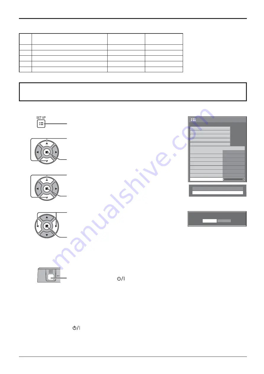
This function allows you to reset the unit to the factory setting.

1

2

3

4

Press to display the Setup menu.

Press to select “OSD Language”.

Press for more than 3 seconds.

Press to select “Shipping”.

Press to display the Shipping menu.

Press to select “YES”.

Press to con rm.

Applicable Input Signals

Video input (VIDEO)

Signal name

Horizontal

Vertical

frequency(kHz)

frequency(Hz)

1

NTSC

15.73

59.94

2

PAL

15.63

50.00

3

PAL60

15.73

59.94

4

SECAM

15.63

50.00

5

Modi ed NTSC

15.73

59.94

1/2

Signal

Off

Standby save

On

PC Power management

Off

DVI-D Power management

Off

OSD Language

English (UK)

Component/RGB-in select

RGB

Power save

Setup

Screensaver

Extended life settings

Input label

3D Settings

No signal power off

Disable

No activity power off

Disable

5

Wait for 10 seconds.

Press the power switch (

) on main unit to turn the power off.

6

Summary of Contents for TH-42PF30W

Page 1: ...Model No TH 42PF30W TH 50PF30W Operating Instructions High De nition Plasma Display TQB4TC0115 Please read these instructions before operating your set and retain them for future reference English ...

Page 2: ...djustments 28 Advanced settings 29 Picture Pro les 30 Saving pro les 31 Loading pro les 32 Editing pro les 32 Sound Adjustment 33 SDI Sound Output 33 PRESENT TIME Setup Set up TIMER 34 PRESENT TIME Setup 34 Set up TIMER 34 3D Settings 35 Screensaver For preventing image retention 36 Setup of Screensaver Time 37 Reduces screen image retention 38 Extended life settings 38 Reduces power consumption 4...

Page 3: ...ng type power plug This plug will only t an earthing type power outlet This is a safety feature If you are unable to insert the plug into the outlet contact an electrician Do not defeat the purpose of the earthing plug 4 To prevent electric shock ensure the earthing pin on the AC cord power plug is securely connected CAUTION This appliance is intended for use in environments which are relatively f...

Page 4: ...h items such as newspapers table cloths and curtains For suf cient ventilation If using the pedestal optional accessory leave a space of 10 cm or more at the top left and right and 7 cm or more at the rear and also keep the space between the bottom of the display and the oor surface If using some other setting up method follow the manual of it If there is no speci c indication of installation dime...

Page 5: ...wer supply plug with wet hands Doing so may cause electric shocks Do not do anything that may damage the power cable When disconnecting the power cable pull on the plug body not the cable Do not damage the cable make any modi cations to it place heavy objects on top of it heat it place it near any hot objects twist it bend it excessively or pull it To do so may cause re and electric shock If the p...

Page 6: ...from direct or re ected light from your Plasma Display Cleaning and maintenance The front of the display panel has been specially treated Wipe the panel surface gently using only a cleaning cloth or a soft lint free cloth If the surface is particularly dirty wipe with a soft lint free cloth which has been soaked in pure water or water in which neutral detergent has been diluted 100 times and then ...

Page 7: ...ng Someone in authority should responsibly convey the precautions for use of the 3D Eyewear to the user 3D Eyewear Do not drop exert pressure on or step on the 3D Eyewear Always store the 3D Eyewear in the case provided when not in use Be careful of the tips of the frame when putting on the 3D Eyewear Be careful not to trap a nger in the hinge section of the 3D Eyewear Pay special attention when c...

Page 8: ...distance View from at least the recommended distance 3 times the effective height of the screen Recommended distance TH 42PF30W 1 6m TH 50PF30W 1 9m When the top and bottom area of the screen is blackened such as movies view the screen at a distance 3 times further than the height of the actual image That makes the distance closer than above recommended gure 3D Eyewear Use Before using the 3D Eyew...

Page 9: ...e batteries for longer life Precaution on battery use Incorrect installation can cause battery leakage and corrosion that will damage the remote control transmitter Disposal of batteries should be in an environment friendly manner Observe the following precaution 1 Batteries shall always be replaced as a pair Always use new batteries when replacing the old set 2 Do not combine a used battery with ...

Page 10: ...ntil it clicks Note Make sure that the AC cord is locked on both the left and right sides AC cord xing Unplug the AC cord Unplug the AC cord pressing the two knobs Note When disconnecting theAC cord be absolutely sure to disconnect theAC cord plug at the socket outlet rst While pressing the lever insert the core wire Black Red Return the lever Black Red hole To loosen hooks To remove from the unit...

Page 11: ...onnect the 3D IR TRANSMITTER optional accessory SERIAL Control the Plasma Display by connecting to PC see page 14 Y PB PR OUT PR PB Y AUDIO OUT R L VIDEO OUT AUDIO OUT R L Notes Change the Component RGB in select setting in the Setup menu to Component when Component signal connection or RGB when RGB signal connection see page 48 Signals input to COMPONENT RGB IN terminals correspond to Sync on G o...

Page 12: ...al Name Pin No Signal Name 1 T M D S data 2 13 2 T M D S data 2 14 5 V DC 3 T M D S data 2 shield 15 Ground 4 16 Hot plug detect 5 17 T M D S data 0 6 DDC clock 18 T M D S data 0 7 DDC data 19 T M D S data 0 shield 8 20 9 T M D S data 1 21 10 T M D S data 1 22 T M D S clock shield 11 T M D S data 1 shield 23 T M D S clock 12 24 T M D S clock Notes Additional equipment and cables shown are not supp...

Page 13: ... of connection Some PC models cannot be connected to the set There is no need to use an adapter for computers with DOS V compatible Mini D sub 15P terminal The computer shown in the illustration is for example purposes only Additional equipment and cables shown are not supplied with this set Do not set the horizontal and vertical scanning frequencies for PC signals which are above or below the spe...

Page 14: ...ponse for the rst command to come from this unit before sending the next command If an incorrect command is sent by mistake this unit will send an ER401 command back to the computer S1A and S1B of Command IMS are available only when a dual input terminal board is attached Communication parameters Signal level RS 232C compliant Synchronization method Asynchronous Baud rate 9600 bps Parity None Char...

Page 15: ...n the Plasma Display is on or in standby mode Note During operation of the power management function the power indicator turns orange in the power off state Connecting the plug to the Wall Outlet Notes Main plug types vary between countries The power plug shown at right may therefore not be the type tted to your set When disconnecting the AC cord be absolutely sure to disconnect the AC cord plug a...

Page 16: ... Options menu 3D Safety Precautions see page 56 Power On Message see page 55 1 Select the language 2 Set 1 Select DAY or PRESENT TIME 2 Setup DAY or PRESENT TIME 1 For vertical installation select Portrait 2 Set 1 Select Set 2 Set When 3D images will be viewed by unspeci ed number of people or used for commercial applications someone in authority should convey the following precautions These preca...

Page 17: ...back from the equipment which has been connected to the Plasma Display Input signals will change as follows PC COMPONENT DVI HDMI VIDEO PC PC input terminal in PC IN VIDEO Video input terminal in AV IN VIDEO COMPONENT Component or RGB input terminal in COMPONENT RGB IN HDMI HDMI input terminal in AV IN HDMI DVI DVI input terminal in DVI D IN COMPONENT may be displayed as RGB depending on the setti...

Page 18: ...e 20 24 Remote control sensor Main Power On Off Switch Power Indicator The Power Indicator will light Power OFF Indicator not illuminated The unit will still consume some power as long as the power cord is still inserted into the wall outlet Standby Red Orange When Slot power is set to On See page 55 Orange Depending on the type of the function board installed when the power is supplied to the slo...

Page 19: ...reen see page 25 SET UP button see page 34 SOUND button see page 33 Volume Adjustment Press the Volume Up or Down button to increase or decrease the sound volume level R button see page 24 Press the R button to return to previous menu screen OFF TIMER button The Plasma Display can be preset to switch to stand by after a xed period The setting changes to 30 minutes 60 minutes 90 minutes and 0 minut...

Page 20: ...the copyright holder The aspect mode changes each time the ENTER button is pressed 4 3 Zoom 16 9 For PC signal input For SD signal input 525 480 60i 60p 625 575 50i 50p 4 3 Zoom1 16 9 Zoom2 Zoom3 14 9 Just Notes The aspect mode is memorized separately for each input terminal Do not allow the picture to be displayed in 4 3 mode for an extended period as this can cause a permanent image retention to...

Page 21: ... in the image being displayed Return to normal display quit Digital Zoom Press to exit from the Digital Zoom The cursor will move Notes When power goes OFF including Off Timer operation Digital Zoom terminates The Digital Zoom function cannot be selected while in the following operation state When MULTI DISPLAY Setup is On see page 44 When Portrait Setup is On see page 46 When Screensaver except f...

Page 22: ...nts Use fully wired HDMI compliant cable For the settings of the player read the manual of the player If you use the non 3D compatible player the images will be displayed without 3D effect To view the contents of 3D formats other than Frame Sequential with 3D effect Match the picture format in 3D Picture Format see page 35 before viewing You can view Side by Side and Top and Bottom with 3D effect ...

Page 23: ...yewear is turned off automatically Check that there are no obstacles between the 3D IR TRANSMITTER and the 3D Eyewear or that the 3D Eyewear is placed inside the coverage area If the 3D Eyewear stops receiving the infrared signal for about 5 minutes the 3D Eyewear will be turned off automatically There is something wrong with the 3D images Switch Reverse and Normal under 3D Picture Sequence in 3D ...

Page 24: ...Sound menu see page 28 32 25 0 0 0 5 Picture Normal Normalise Normal Brightness Sharpness Picture Mode Colour Contrast Hue Advanced settings Memory save White balance Normal Memory load Memory edit 1 2 Signal Screensaver Extended life settings Input label Off Standby save On PC Power management Off DVI D Power management Off OSD Language English UK Component RGB in select RGB Power save Setup 3D S...

Page 25: ...signal as an example H Pos V Pos H Size V Size Dot Clock and Clock Phase are automatically corrected This setting is enabled under the following conditions This setting is not activated during Multiple display Portrait display or Digital Zoom When inputting an analog signal Component PC This setting is enabled if Component RGB in select see page 48 in Setup menu is RGB When inputting a digital sig...

Page 26: ...Hz or higher Dot Clock and Clock Phase cannot be automatically corrected When digital signal input Dot Clock and Clock Phase cannot be made Auto Setup may not work when a cropped or dark image is input In such case switch to a bright image with borders and other objects are clearly shown and then try auto setup again Depending on the signal out of alignment may occur after Auto Setup Carry out ne ...

Page 27: ...able input signal 1125 1080 50i 60i 24sF 24p 25p 30p 50p 60p 1250 1080 50i Select Off when ickering is shown around the image H Size and V Size cannot be adjusted when On is selected Off On 1 1 Pixel Mode 2k1k For 2k1k signals When the input signal is a 2k1k signal 2048 1080 24p 2048 1080 24sF the display size is adjusted as follows Off On Left On Center On Right Note 2k1k signals can only be rece...

Page 28: ...m Press or button to switch between modes Normal Monitor Dynamic Cinema Normal For viewing in standard evening lighting environments This menu selects the normal levels of Brightness and Contrast Dynamic For viewing in brighter environments This menu selects higher than normal levels of Brightness and Contrast Cinema Ideal for movies Monitor For use when creating broadcast or movie content With th...

Page 29: ...ss Less More Adjusts picture sharpness Notes Carry out W B adjustment as follows 1 Adjust the white balance of the bright sections using the W B High R W B High G and W B High B settings 2 Adjust the white balance of the dark sections using the W B Low R W B Low G and W B Low B settings 3 Repeat steps 1 and 2 to adjust Steps 1 and 2 affect each other s settings so repeat each step in turn to make ...

Page 30: ...URE MEMORY2 MEMORY3 MEMORY4 MEMORY8 18 0 0 0 3 Picture Normal Normalise Dynamic Brightness Sharpness Picture Mode Colour Contrast Hue Advanced settings Memory save White balance Normal Memory load Memory edit Save pro les page 31 Load pro les page 32 Edit pro les page 32 25 0 0 0 5 Picture Normal Normal Normal Normalise Brightness Sharpness Picture Mode Colour Contrast Hue Advanced settings White ...

Page 31: ...ring pro le names Pro le names can be up to 40 characters To enter text select characters in the on screen keyboard Edit the default profile name in the text box as desired Memory name input Ok A MEMORY1 B C D E F G H I J K L M All delete N O P Q R S T U V W X Y Z Delete Space a b c d e f g h i j k l m n o p q r s t u v w x y z 0 1 2 3 4 5 6 7 8 9 _ ˆ Cancel 1 select 2 set Example Specifying MY PI...

Page 32: ...ect All delete Memory delete 2 3 MEMORY2 MEMORY3 All delete 4 MEMORY4 MEMORY1 1 1 select 2 set 4 Select Ok Memory delete Cancel Delete the MEMORY1 data Ok 1 select 2 set Renaming pro les 1 In the Picture menu select Memory edit Memory save Memory load Memory edit 1 select 2 access 2 Select Memory name change Memory edit Memory name change Memory delete 1 select 2 set 3 Select the pro le to rename ...

Page 33: ...TY FB30DHD3D 2 2 Sound Out Left Channel Right Channel Channel 1 Channel 1 Off Level Meter Off SDI Sound Output Item Details Left Channel Channel 1 to Channel 16 Selects left audio channel Right Channel Channel 1 to Channel 16 Selects right audio channel Sound Out On Off On Enables audio output Off Disables audio output Level Meter Off 1 8ch 9 16ch Sets audio channels to show in the audio level met...

Page 34: ...Back Notes Pressing or button once changes PRESENT TIME 1 minute Pressing or button continuously changes PRESENT TIME by 15 minutes Press to select Set Press to store PRESENT TIME Setup Notes Set cannot be selected unless PRESENT TIME is set Unless setting the present time other than 99 99 DAY and PRESENT TIME cannot be set The settings of DAY and PRESENT TIME are reset when leaving the display tu...

Page 35: ...om One of the formats of the 3D standard Select these formats as necessary Native Displays the input signal as it is Use to identify the format type of the input signal 3D Picture Sequence Reverse Normal This function calibrates the timing to switch the right and left images as well as the timing to switch the shutter of right and left 3D Eyewear Select Reverse if you feel that the sense of depth ...

Page 36: ...ed off the Scrensaver will be deactivated Press to select Mode Press to select each mode items Off Interval OperateswhenPeriodicTimeandOperating Time are setup and those times arrive Time Designation Operates when Start Time and Finish Time are setup and those times arrive Standby after SCR Saver Operates while Screensaver duration and display enters standby mode On Operates when Start is selected...

Page 37: ...de is On or Off Press to select Start Time Finish Time when Time Designation is selected Press to select Periodic Time Operating Time when Interval is selected Press to select Screensaver duration when Standby after SCR Saver is selected Press to setup button Forward button Back Note Timer function will not work unless PRESENT TIME is set Notes Pressing or button once changes the Time 1 minute How...

Page 38: ...ay ash alternate black white depending on the picture being shown on the screen Using Cinema mode will reduce such ashing side panel 4 3 Screen Display image retention Reduces screen image retention The following settings are setup to reduce image retention Image Retention Reduction Menu Extended life settings enables you to set the following 5 menus Image Retention Reduction Menu as recommended v...

Page 39: ...ettings Custom settings Reset Extended life settings 1 select 2 access 2 Select the input to apply the settings Apply to current input Apply to all inputs Extended life settings 1 select 2 set 3 Select Yes Apply to current input No Yes Extended life settings 1 select 2 set NANODRIFT Saver Moves the display position of the screen slightly to reduce image retention on the display panel Low High NANO...

Page 40: ...mended settings 1 select 2 adjust When a menu is locked it is grayed out and cannot be set Picture Mode and Contrast will no longer be able to set in the Picture menu and they are labeled with icon to indicate their locked status Also Normalise Memory save and Memory load are not available 30 0 0 0 5 Picture Normal Normalise Brightness Sharpness Picture Mode Colour Contrast Hue Advanced settings M...

Page 41: ...pictures sync signal are detected for 30 or so seconds during DVI signal input Power is turned off standby the power indicator lights up orange When pictures sync signal are subsequently detected Power is turned on the power indicator lights up green Notes This function operates only during DVI signal input This function is invalid during input from DVI D Terminal Board TY FB11DD and Dual DVI D Te...

Page 42: ...ONENT DVD1 DVD2 DVD3 DVD4 Blu ray1 Blu ray2 Blu ray3 Blu ray4 CATV VCR STB Skip HDMI HDMI DVD1 DVD2 DVD3 DVD4 Blu ray1 Blu ray2 Blu ray3 Blu ray4 CATV VCR STB Skip DVI DVI DVD1 DVD2 DVD3 DVD4 Blu ray1 Blu ray2 Blu ray3 Blu ray4 CATV VCR STB Skip PC PC DVD1 DVD2 DVD3 DVD4 Blu ray1 Blu ray2 Blu ray3 Blu ray4 CATV VCR STB Skip Skip The INPUT button press will skip its input 1 SLOT INPUT is displayed ...

Page 43: ...ntrol and the display style of on screen menu for vertical installation Press to display the Setup menu Press to select Display orientation Press to select Landscape or Portrait Press to exit from adjust mode 1 2 3 Notes Turn up the power switch for the upward direction when you set Display vertically When you change this setting fan control and panel drive control will be switched as the power is...

Page 44: ...his mode of operation each plasma display has to be set up with a Display number to determine its location Note During Multi display the 3D images are displayed as 2D images Example group of 16 4 4 group of 4 2 2 group of 9 3 3 group of 25 5 5 Item Details MULTI DISPLAY Setup Select On or Off Note If you set MULTI DISPLAY Setup to On Portrait Setup will be unavailable Horizontal Scale Select 1 2 3...

Page 45: ...ss the button on the remote control Press one of for the tens digit setting Press one of for the units digit setting 4 Notes The numbers in 2 3 and 4 should be set up quickly Adjustable ID number range is 0 99 If a number button is pressed more than two times the rst two numbers become the ID number for the remote control ID Cancellation Press button on remote control This has the same effect as p...

Page 46: ...splays Suitable for moving image display To show joints between displays Suitable for still image display On Off Notes When using the Portrait function with displays set vertically Display orientation in Setup menu has to be set to Portrait see page 43 Turn up the power switch for the upward direction when you set Display vertically During Portrait display the 3D images are displayed as 2D images ...

Page 47: ...s set at 16 9 and cannot be changed HD signal 1125 1080 60i 50i 60p 50p 24p 25p 30p 24sF 750 720 60p 50p 1250 1080 50i When Viewing Area is 16 9 the aspect mode is set to 16 9 5 Viewing Area Set a mode of image division for Portrait function Location Set a location of image to be displayed for Portrait function When Portrait Setup is On Display the image of the selected location When Portrait Setu...

Page 48: ... to exit from adjust mode Note Make setting of the selected input terminal COMPONENT RGB IN or PC IN 3 YUV RGB in select Select to match the signals from the source connected to the DVI input terminals YUV signals YUV RGB signals RGB 1 2 Press to display the Setup menu Press to select the YUV RGB in select Press to select the desired mode YUV RGB Press to exit from adjust mode Notes Selection may ...

Page 49: ...ut signal On Off Note When On this setting only affects NTSC input signals Colour system Auto SECAM M NTSC NTSC PAL Set the colour system to match the input signal When Auto is set Colour system will be automatically selected from NTSC PAL SECAM M NTSC To display PAL60 signal select Auto or PAL If the picture image becomes unstable With the system set on Auto under conditions of low level or noisy...

Page 50: ... HD SDI Terminal Board TY FB11DHD is selected FRAME CREATION Automatically compensates the picture frame rate and removes juddering movements to make the images smooth Off Min Mid Max Min can be selected during 2D viewing Note Depending on the contents images may be noisy To prevent the noise change the setting 3D Refresh Rate Reduces juddering or icker of image due to lighting interference during...

Page 51: ... NR 1 Press to select P NR Mosquito NR or Block NR Press to select Off Min Mid Max 2 P NR Automatically reduces unwanted picture noise Mosquito NR Reduces mosquito noise around subtitles on MPEG videos Block NR Reduces block noise when playing MPEG videos Note Noise reduction cannot be adjusted while a PC signal is being applied Advanced NR Displays the frequency and the type of the current input ...

Page 52: ...ion To obtain an IP address automatically using a DHCP server set this to On If DHCP server is not used set this to Off IP address IP address display and setting Enter an IP address if DHCP server is not used Subnet mask Subnet mask display and setting Enter a subnet mask if DHCP server is not used Gateway Gateway address display and setting Enter a gateway address if DHCP server is not used Port ...

Page 53: ...stalled SLOT INPUT A and SLOT INPUT B are displayed 2 COMPONENT may be displayed as RGB depending on the setting of Component RGB in select see page 48 Notes Only the adjusted signal is displayed see page 17 This menu is available only when Input lock is Off Initial VOL level Press button to adjust the volume when the unit is turned on Off On Off Sets normal volume On Sets your preferred volume No...

Page 54: ... failure or after plugging off and in again Normal Power returns in as the same state as before the power interruption Standby Power returns in standby mode Power Indicator red orange On Power returns in power On Power Indicator green Note When using multiple displays Standby is preferred to be set in order to reduce a power load ID select Sets panel ID number when panel is used in Remote ID or Se...

Page 55: ...and also the power is being supplied to a terminal board the unit will start supplying the power to the board with time delay according to the setting The power indicator lights up red rst and it turns orange when the power starts being supplied to the board Clock Display Off Not display the clock On Display the clock The clock is displayed at the lower left of the screen when button is pressed No...

Page 56: ...You can set the program from 1 to 7 indicates unset 2 Press to select Program Edit Press to show the Program Edit screen Press to select Program Press to change the program numbers 1 7 4 3 Press ACTION button Program Edit screen Normalization When both main unit buttons and remote control are disabled due to the Button lock Remocon User level or Remote ID adjustments set all the values Off so that...

Page 57: ...me of timer indicates unset Command numbers Options Adjustments Press to select Command No Press to select a command number 6 Press to select Time Command Press to set each item Time Set the time to execute a command program Pressing or button once changes Time 1 minute Pressing or button continuously changes Time by 15 minutes Command Select a command to execute at the set time This unit has 64 c...

Page 58: ...SLOT INPUT A VIDEO COMPONENT DVI PC NO AUDIO SLOT INPUT B SLOT INPUT B VIDEO COMPONENT DVI PC NO AUDIO VIDEO SLOT INPUT A SLOT INPUT B VIDEO COMPONENT DVI PC NO AUDIO COMPONENT SLOT INPUT A SLOT INPUT B VIDEO COMPONENT DVI PC NO AUDIO HDMI SLOT INPUT A SLOT INPUT B VIDEO COMPONENT HDMI DVI PC NO AUDIO DVI SLOT INPUT A SLOT INPUT B VIDEO COMPONENT DVI PC NO AUDIO PC SLOT INPUT A SLOT INPUT B VIDEO ...

Page 59: ...anel available as an option is set up Set Touch Panel mode to On Select Calibration mode and then press This setting is used in calibrating a touch panel You can con gure the setting if Touch Panel mode is On Calibration mode Touch Panel settings Settings when using Touch Panel ª Calibration mode 1 select 2 adjust 1 select 2 set NANODRIFT Saver in Touch Panel mode On The value set for NANODRIFT tu...

Page 60: ...X use category 5 LAN cable Touching the LAN terminal with a statically charged hand body may cause damage due to its discharge Do not touch the LAN terminal or a metal part of the LAN cable For instructions on how to connect consult your network administrator Network function of the unit can control the unit in the same way as serial control from a network Supported commands Commands used in the s...

Page 61: ... mute AVMT Shutter control query Parameter 11 Picture Off picture on mute 21 Audio Off audio on mute 30 Shutter mode Off picture and audio mute deactivated 31 Shutter mode On picture and audio on mute ERST Error status query Parameter First byte Means fan error 0 or 2 Second byte 0 Third byte 0 Fourth byte 0 Fifth byte 0 Sixth byte Means other error 0 or 2 Meaning of the 0 2 settings 0 Error is no...

Page 62: ... Safari menu click Preferences General screen is displayed 2 From the Advanced tab click the Change Settings button next to Proxies Click Proxies and set up a proxy server 3 Deselect the Web Proxy and Automatic Proxy Con guration boxes 4 Click Apply Now Enable JavaScript 1 Display Security of Safari 2 Select Enable JavaScript under Web content 1 Start your Web browser 2 Enter the IP address set wi...

Page 63: ...creen OPTION CONTROL screen Click BASIC CONTROL from the menu Unit status and buttons to change settings are displayed Item Details POWER Switch ON OFF of the unit power INPUT SELECT Switch the input signals Displayed buttons vary according to the connection status of the video device AUDIO MUTE Switch ON OFF of the sound mute ASPECT Switch the screen modes Click OPTION CONTROLfrom the menu Comman...

Page 64: ...ssword is Panasonic Up to 32 alphanumeric characters can be used for a password When the password is changed properly Password has changed message is displayed Item Details OLD PASSWORD Enter the old password NEW PASSWORD Enter the new password NEW PASSWORD RETYPE Enter the password entered in NEW PASSWORD for con rmation SAVE Save the new password The con rmation screen is displayed Click OK to c...

Page 65: ...ment No signal power off and No activity power off in the Setup menu Any of them may be set to On Enable see page 41 Power indicator is blinking in red There is possibility of malfunction Please contact an Authorized Service Center This Plasma Display uses special image processing Hence a slight time lag may occur between image and audio depending on the type of input signal However this is not a ...

Page 66: ...the screen is slightly elongated 4 3 4 3 Pictures with a 4 3 aspect ratio are displayed with their original aspect ratio Side panels are displayed at the left and right edges of the screen 4 3 1 4 3 2 The pictures with a 4 3 aspect ratio among the 16 9 aspect ratio signals are displayed with their original aspect ratio The left and right edges of the pictures are masked with side panels 4 3 Full 4...

Page 67: ...51 89 32 1 024 768 60 Hz 48 36 60 00 65 0 65 0 33 1 024 768 70 Hz 56 48 70 07 75 0 34 1 024 768 75 Hz 60 02 75 03 78 75 35 1 024 768 85 Hz 68 68 85 00 94 5 36 1 066 600 60 Hz 37 64 59 94 53 0 53 0 37 1 152 864 60 Hz 53 70 60 00 81 62 38 1 152 864 75 Hz 67 50 75 00 108 0 39 1 280 768 60 Hz 47 70 60 00 80 14 40 1 280 960 60 Hz 60 00 60 00 108 0 41 1 280 960 85 Hz 85 94 85 00 148 5 42 1 280 1 024 60 ...

Page 68: ...menu Press to select OSD Language Press for more than 3 seconds Press to select Shipping Press to display the Shipping menu Press to select YES Press to con rm Applicable Input Signals Video input VIDEO Signal name Horizontal Vertical frequency kHz frequency Hz 1 NTSC 15 73 59 94 2 PAL 15 63 50 00 3 PAL60 15 73 59 94 4 SECAM 15 63 50 00 5 Modi ed NTSC 15 73 59 94 1 2 Signal Off Standby save On PC ...

Page 69: ...MS SL1 Input select SLOT INPUT 40 IMS S1A Input select SLOT INPUT A 41 IMS S1B Input select SLOT INPUT B 42 IMS VD1 Input select VIDEO 43 IMS YP1 Input select COMPONENT 44 IMS HM1 Input select HDMI 45 IMS DV1 Input select DVI 46 IMS PC1 Input select PC 47 48 49 50 51 52 53 54 55 OSP SCR0 Screen Saver Scrolling bar only OFF 56 OSP SCR1 Screen Saver Scrolling bar only ON 57 POF Power OFF 58 PON Powe...

Page 70: ...le with PJLink AV IN VIDEO AUDIO L R BNC RCA Pin jack 2 1 0 Vp p 75 0 5 Vrms HDMI TYPE A Connector COMPONENT RGB IN Y G PB CB B PR CR R AUDIO L R BNC BNC BNC RCA Pin jack 2 with sync 1 0 Vp p 75 0 7 Vp p 75 0 7 Vp p 75 0 5 Vrms DVI D IN AUDIO DVI D 24 Pin Content Protection Stereo mini jack M3 1 Compliance with DVI Revision 1 0 Compatible with HDCP 1 1 0 5 Vrms Shared with PC IN PC IN AUDIO High D...

Page 71: ...71 Memo ...

Page 72: ...y nor the names of its contributors may be used to endorse or promote products derived from this software without specific prior written permission THIS SOFTWARE IS PROVIDED BY THE REGENTS AND CONTRIBUTORS AS IS AND ANY EXPRESS OR IMPLIED WARRANTIES INCLUDING BUT NOT LIMITED TO THE IMPLIED WARRANTIES OF MERCHANTABILITY AND FITNESS FOR A PARTICULAR PURPOSE ARE DISCLAIMED IN NO EVENT SHALL THE REGEN...

Reviews: