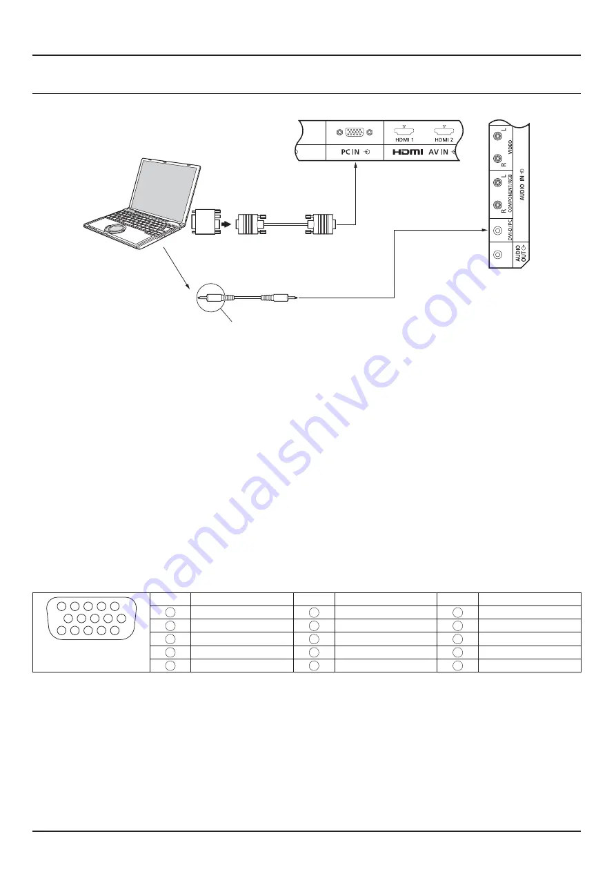
background image

16

Connections

PC Input Terminals connection

(Male)

RGB

Mini D-sub 15p

Stereo mini plug (M3)

Audio

Connect a cable which matches
the audio output terminal on the computer.

(Female)

COMPUTER

Conversion adapter 
(if necessary)

Shared with DVI-D IN.

Notes:

} 4 #    ()(-; %%;/

()(07 %*;/!/  #( %*;;
"

} The display resolution is a maximum of 1,440‚%,080     „0$-…%8*;‚%;7;

     „1?^^…+(     #
#   (  

} <4  4*I #+(  #  4*I #

need to make setting changes to the computer at the time of connection.

} E<4 #    

}   (  =E>T #X#%2< 

}     (

} 9 ) #    

}      ()(<4##

frequency range.

Signal Names for Mini D-sub 15P Connector

10 

15 14 13 12 11 

Pin Layout for PC Input 

Terminal

Pin No. E&

Pin No. E&

Pin No. E&

1

'

6

Y&!Y"

11

&4!  "

2

Y

7

Y&!Y"

12

E9

3

B

8

Y&!Y"

13

/>Ew&4

4

&4!  "

9

ƒ2T4

14

VD

5

Y&!Y"

10

Y&!Y"

15

E4^

Summary of Contents for TH-42LF6U

Page 1: ...H 47LF6U TH 47LF60U TH 55LF6U TH 55LF60U Operating Instructions FULL HD LCD Display Before connecting operating or adjusting this product please read these instructions completely Please keep this manual for future reference English ...

Page 2: ...o not remove cover or back to tell the user that parts inside the product are a risk of electric shock to persons triangle is intended to tell the user that important operating and servicing instructions are in the WARNING moisture WARNING ture Do not defeat the purpose of the grounding plug ...

Page 3: ...3 Important Safety Instructions Keep these instructions 0 1 2 3 4 5 6 7 8 9 9 A 0 E A 2 94 ...

Page 4: ...ents 30 9 T9 4W EW YE 31 SOUND Adjustment 32 PRESENT TIME SETUP SET UP TIMER 33 WEW XW EW 33 EW XW 34 SCREENSAVER For preventing image retention 35 E E4 WW E9TW 36 WOBBLING 36 NO ACTIVITY POWER OFF 37 ECO MODE SETTINGS 38 Customizing the Input labels 39 Selecting the On Screen Menu Language 40 Customizing the On Screen Menu Display 40 SET UP for MULTI DISPLAY 41 X E 9w 41 4 1 42 SET UP for Input S...

Page 5: ...anasonic Corp of North America could void the user s authority to operate this device FCC Declaration of Conformity X 0 13 05 13 22 13 0 13 05 13 22 13 4 9 5 4 E E 4 4 9 7 85 0 8 CANADIAN NOTICE 4 I 4 4WE NOTE Image retention may occur If you display a still picture for an extended period the image might remain on the Trademark Credits TY9 I X 4 Microsoft T and Internet Explorer are the registered...

Page 6: ...y Do not bring your hands face or objects close to the ventilation holes of the Display I A A A Be sure to disconnect all cables before moving the Display X Disconnect the power plug from the wall outlet as a safety precaution before carrying out any cleaning Electric shocks can result if this is not done Clean the power cable regularly to prevent it from becoming dusty I Note Image retention may ...

Page 7: ...on 110 127 V AC 50 60 Hz Ensure that the mains plug is easily accessible Do not use any power supply cord other than that provided with this unit Securely insert the power cord plug as far as it will go Do not handle the power cord plug with wet hands Doing so may cause electric shocks Do not do anything that might damage the power cable When disconnecting the power cable hold the plug not the cab...

Page 8: ...ction 4 X transmitter 9wI 38 Batteries for the remote control transmitter 99 E 94 4 Warranty card 1 X Warranty Remote Control Batteries Requires two AA batteries 1 Pull and hold the hook then open 2 3 99 Helpful Hint 1 9 Precaution on battery use Observe the following precautions 1 I 9 2 3 4 9 4 5 I 6 I ...

Page 9: ...9 Ceiling Suspension w X 22 13 22 13 W W Note E installation professional Display ...

Page 10: ...ions AC cord accessory Using the clamper E 1 2 Attach the clamper To remove from the unit Keep side snaps hole Bundle the cables snaps hooks E tip in the hooks To loosen Keep pushing Insert the clamper in a hole ...

Page 11: ...onnect the audio output of a device 4 X W YI 0 VIDEO IN VIDEO Composite Video Input Terminal 0 COMPONENT RGB IN PR R PB B Y G 4 YI T 0 DVI D IN DVI D OUT T Terminal 2 LAN DIGITAL LINK 4 Y 9 9 sends video and audio signals via the Y 9 8 22 23 IR IN IR OUT remote control connects other display from this IN OUT port 7 AUDIO OUT Connect to sound equipment AUDIO IN VIDEO Connect the audio output of a d...

Page 12: ...12 Connections AUDIO OUT connection Note 9 9 Stereophonic sound code audio equipment line in Stereo mini plug M3 ...

Page 13: ...MI cable HDMI AV OUT DVD player Pin assignments and signal names 19 3 1 4 2 18 Pin No E Pin No E 1 X E 11 X E 4 E 2 X E E 12 X E 4 3 X E 13 CEC 4 X E 14 4 5 X E E 15 E4 6 X E 16 E 9 7 X E 17 4 4W4 Y 8 X E E 18 2 T 4 9 X E 19 Hot Plug Detect 10 X E 4 Note 9 X ...

Page 14: ...B IN connection Note 9 R L R L AUDIO OUT AUDIO OUT RGB OUT Y PB PR OUT VIDEO OUT RCA BNC Adapter plug RCA BNC Adapter plug DVD Player VCR Computer RGB Camcorder DVD Player Notes 4 4 X W YI EW W4 EW 4 X W 4 X W YI YI 0 9 YI 4 X W YI Ew 4 Y ...

Page 15: ...ion 4 First LCD Display Second LCD Display Third and subsequent LCD displays DVI video cable PC with DVI D video out Notes 4 7 DVI D Input Connector Pin Layouts 4 Pin No E Pin No E 1 X E 13 2 X E 14 2 T 4 3 X E E 15 Y 4 16 Hot Plug Detect 5 17 X E 6 DDC Clock 18 X E 7 DDC Data 19 X E E 8 20 9 X E 21 10 X E 22 X E 4 E 11 X E E 23 X E 4 12 24 X E 4 Note 9 ...

Page 16: ...ed with DVI D IN Notes 4 07 The display resolution is a maximum of 1 440 080 0 8 7 1 4 4 I 4 I need to make setting changes to the computer at the time of connection E 4 E T X 2 9 4 frequency range Signal Names for Mini D sub 15P Connector 1 6 7 8 3 9 4 5 10 15 14 13 12 11 2 Pin Layout for PC Input Terminal Pin No E Pin No E Pin No E 1 6 Y Y 11 4 2 Y 7 Y Y 12 E 9 3 B 8 Y Y 13 Ew 4 4 4 9 2 T 4 14 V...

Page 17: ...play Male COMPUTER D sub 9p Female Female RS 232C Straight cable Female Female Female Notes E 4 computer to the Display 9 E 4 2 1 2 through 8 EW 9 E 4 documentation for the computer application for details Signal names for SERIAL IN terminal 6 7 8 9 1 3 4 5 2 EW 9 Terminal Pin No E 2 3 TXD 4 5 Y 6 E 7 8 E 1 9 NC Communication parameters E E 4 E 9 Baud rate 83 Parity None Character length 7 E 1 ...

Page 18: ...C1 C2 C3 P1 P2 P3 P4 P5 ETX Notes W 0 4 9 E 4 instructions on command usage command only Command Command Parameter Control details PON None POF None 11 9T T 9X 0 9 X W 11 1 9 X W XE None 9T 9T HM1 HM2 DV1 PC1 DL1 T W T W 4 X W YI 4 X X X X T T 4 4 Y 9 9X None X FULL X X E X FULL 4 3 X IR IN IR OUT Terminals connection 2 WX W 1 4 WX W E 4 1 4 E 4 First LCD Display Second LCD Display Third LCD Displ...

Page 19: ...19 Connections 9 I W w1I Y 9 terminal Display Connection Terminals Control Computer When a Panasonic ET YFB100 is used Computer Video Cassette Recorder DVD Player Notes Y 9 E 07 2 1 Y 9 23 ...

Page 20: ...AC cord plug to the Display Connecting the plug to the Wall Outlet Notes 94 94 Power Indicator Green Power Indicator Remote Control Sensor Power switch 1 Press the Power Indicator Red standby 2 Press the Power Indicator Green 3 Note ...

Page 21: ...w 2 E 9w WEW XW 1 9w PRESENT TIME SETUP PRESENT TIME OF DAY MON 99 99 SET PRESENT TIME OF DAY 99 99 DAY MON 1 E EW 2 E PRESENT TIME SETUP PRESENT TIME OF DAY MON 99 99 SET PRESENT TIME OF DAY 10 00 DAY TUE Notes 6 9 E 9 Y 9YW 0 WEW XW EW Power ON warning message No activity power off Precautions 6 94 T w W 116 E W 9I W 94 T w W 11 EW W 9I W 5 X 2 ...

Page 22: ...DMI1 HDMI2 Component VIDEO DVI DIGITAL LINK HDMI1 HDMI2 X X 9T X VIDEO Video input terminal in VIDEO IN Component 4 YI 4 X W YI PC PC input terminal in PC IN DVI T T DIGITAL LINK Y 9 Y 9 4 YI 4 X W YI EW W4 0 Notes E on the unit E YI 0 ...

Page 23: ... 07 Y 4 W X9 9YWXW XE 4 E 7 T W X9 9YWXW T E 7 Brightness Sensor Remote control sensor MENU Screen ON OFF W XW 5 T 4 W EW E E E W Volume Adjustment T When the menu screen is displayed 5 Main Power On Off Switch Enter Aspect button 2 5 INPUT button Input signal selection ...

Page 24: ...ITION buttons INPUT button Press to select input signal sequentially ECO MODE ECO Press to change the ECO MODE 7 7 7 FUNCTION buttons FUNCTION 2 Digital Zoom 3 AUTO SETUP button 9 A 7 SET UP button 2 SOUND button Volume Adjustment T sound volume level R button 5 previous menu screen OFF TIMER button 3 8 30 MIN 60 MIN 0 MIN 90 MIN 11 XW X occurs RECALL button W49 the current system status 1 2 9 2 3...

Page 25: ...ress repeatedly to move through the aspect options 4 3 X FULL X from the unit Right side surface Note Aspect mode Picture Enlarged screen Description FULL E 0 3 8 4 3 0 E screen 3 8 panels X 3 8 edges of the pictures are cut off X 3 8 W W ...

Page 26: ... 2 1 EXIT 1 2 3 4 Select the area of the image to be enlarged Press on the enlargement location to select Return to normal display quit Digital Zoom W 3 2 4 1 Display the operation guide During Digital Zoom only the following buttons can be operated E 94 Notes 11 X E 9w EW 0 E4 WW E9TW 2 9 A E E W ...

Page 27: ...IGHTNESS PICTURE MENU PICTURE 0 0 TINT COLOR BACKLIGHT SHARPNESS 50 COLOR TEMP NORMAL FRAME CREATION MAX ADVANCED SETTINGS see page 30 31 SET UP menu 1 2 SIGNAL INPUT LABEL ECO MODE SETTINGS WOBBLING SET UP OFF COMPONENT RGB IN SELECT RGB SCREENSAVER NO ACTIVITY POWER OFF DISABLE OSD LANGUAGE ENGLISH US 2 2 SET UP MULTI DISPLAY SETUP SET UP TIMER PRESENT TIME SETUP MENU DISPLAY DURATION 15 S MENU ...

Page 28: ...ZE CLOCK PHASE H SIZE 1 1 PIXEL MODE DOT CLOCK 0 0 0 0 Note A grayed out 9 A depending on the input signal and the display mode 1 E E W 2 3 4 Note 4 T4 T E E W AUTO SETUP E T E E W T E W 4 4 4 4 9EW A YI 4 4 YI 1 Using Remote Control When 9 EW 9 EW T9 Notes 9 EW A 9 EW 4 9 EW 3 Y9 0 537 3 33 537 3 Y9 X W 02 9 EW 9 EW 9 EW A X9 W 94 A E E W 9 EW perform DOT CLOCK adjustment ...

Page 29: ...OT CLOCK During RGB and PC input signal A OVER SCAN Turn image over scan ON OFF 4 2 2 2 2 3 2 3 2 52 3 52 2 4 T T X ON OFF Notes 11 1 11 E W T E W A 1 1 PIXEL MODE 9 A 2 2 Notes 1 E 8 7 9 2 7 2 60i 24sF 24p 25p 30p 50p 60p E 11 E W T E W A OFF ON Helpful Hint NORMALIZE Normalization E E W 94 X9 W A 4 4 9EW 4 4 ...

Page 30: ...GHTNESS PICTURE MENU PICTURE 0 0 TINT COLOR BACKLIGHT SHARPNESS 50 COLOR TEMP NORMAL FRAME CREATION MAX ADVANCED SETTINGS Press the left or right X9 9 X COOL FRAME CREATION picture Press the left or right OFF MIN MID X9 E 11 X9 W X 11 ADVANCED SETTINGS W A AGC GAMMA INPUT LEVEL ADVANCED SETTINGS NORMAL NORMALIZE W B LOW B W B HIGH R W B LOW R W B LOW G W B HIGH G W B HIGH B 0 2 2 50 50 50 50 50 50...

Page 31: ...A hair COLOR Less More 9 A TINT Y 9 A SHARPNESS Less More 9 A ADVANCED SETTINGS Item Effect Details INPUT LEVEL Less More 9 A GAMMA Up E 4 TW 2 0 2 2 2 6 AGC OFF ON W B HIGH R Less More 9 A W B HIGH G Less More 9 A W B HIGH B Less More 9 A W B LOW R Less More 9 A W B LOW G Less More 9 A W B LOW B Less More 9 A Notes 4 I A 1 9 A I Y I Y Y I Y I 2 9 A I I Y I I 3 1 and 2 to adjust E 1 and 2 6 A A A ...

Page 32: ...ELECT 1 E 2 E A 3 Press to select the menu to adjust Press to exit from adjust mode E Item Details OUTPUT SELECT E W9 W E W 9 W 9 AUDIO MENU STANDARD Emits the original sound DYNAMIC 9 CLEAR 9 BASS 9 A TREBLE 9 A BALANCE 9 A SURROUND E 11 Note 9 I9 9 4W A I9EE WI W E 9 XW Helpful Hint NORMALIZE Normalization E 94 X9 W A ...

Page 33: ...LAY DURATION 15 S MENU TRANSPARENCY 20 EW 2 1 EW XW WEW XW EW EW XW WEW XW EW PRESENT TIME SETUP 99 99 MON PRESENT TIME SETUP PRESENT TIME OF DAY MON 99 99 SET PRESENT TIME OF DAY DAY 9w WEW XW 1 9w 1 2 9w WEW XW 1 9w 1 I Notes Pressing WEW XW 1 9w Pressing WEW XW 1 9w 2 EW WEW XW EW Notes EW WEW XW 1 9w 88 88 9w WEW XW 1 9w 9w WEW XW 1 9w 5 W display 94 ...

Page 34: ...MER E 11 x W X T W ON POWER ON 12 00 VIDEO SET UP TIMER DAY POWER MODE TIME INPUT TIMER FUNCTION PROGRAM 1 MON PRESENT TIME OF DAY MON 0 03 1 select 2 adjust 1 E 2 11 3 E WTW w 9w t 4 E 11 5 E Pressing XW Pressing XW 2 minutes 6 E Notes WEW XW EW ...

Page 35: ...F COMPONENT RGB IN SELECT RGB SCREENSAVER NO ACTIVITY POWER OFF DISABLE OSD LANGUAGE ENGLISH US 2 1 EW E4 WW E9TW E4 WW E9TW 3 MODE selection Press to select the MODE OFF W T9 E 9 E9TW 9 XW 1 9w E 9 XW 1 E XW are set up and those times arrive E 9 Iw 91 W E4 E9TW E4 WW E9TW 9 ON E 9 94 Press to select each mode items START setting 4 X W E 9 E4 WW E9TW E4 WW E9TW To stop the SCREENSAVER under ON pre...

Page 36: ...MODE SCREENSAVER DURATION STANDBYAFTER SCR SAVER 6 15 PRESENT TIME OF DAY MON 15 00 E 9 XW 1 E XW XW 1 9w E 9 E9TW 9 W T9 E4 WW E9TW 9 E 9 Iw 91 W E4 E9TW Press to setup 1 I Notes Pressing 2 Pressing 2 E4 WW E9TW 9 E 9 Iw 91 W E4 E9TW 28 E 9 Iw 91 W E4 E9TW WEW XW 1 9w WOBBLING 9 of image 2 1 3 1 2 SIGNAL INPUT LABEL ECO MODE SETTINGS WOBBLING SET UP OFF COMPONENT RGB IN SELECT RGB SCREENSAVER NO ...

Page 37: ...ING SET UP OFF COMPONENT RGB IN SELECT RGB SCREENSAVER NO ACTIVITY POWER OFF DISABLE OSD LANGUAGE ENGLISH US Press to select the menu to adjust 1 2 3 W 9I W E9I W EW W 9I W Display for 4 hours E NO ACTIVITY POWER OFF 3MIN PRESS ANY KEY TO ABORT 9E 11 W 6 94 T w W 116 Note ...

Page 38: ...E ECO MODE CUSTOM ON E Y 9 W 11 W 9I W 4 W X9 9YWXW T W X9 9YWXW W E9TW EW E Using Remote Control When W4 X W ECO MODE ON Custom settings W4 X W 4 E X NO SIGNAL POWER OFF W 11 W 9I W Note PC POWER MANAGEMENT When no pictures are detected for 30 or so seconds during PC signal input Notes This function operates only during input from PC IN terminal Ew 4 9 DVI D POWER MANAGEMENT T Note This function ...

Page 39: ...L VIDEO Component PC DVI DIGITALLINK VIDEO Component PC DVI DIGITAL LINK HDMI1 HDMI1 HDMI2 HDMI2 9IW 9IW Press to select image input Image input VIDEO T W T T T I I I 49 T T4 E I E Component 4 T T T I I I 49 T T4 E I E PC 4 T T T I I I 49 T T4 E I E DVI T T T T I I I 49 T T4 E I E Y 9 Y 9 T T T I I I 49 T T4 E I E HDMI1 X T T T I I I 49 T T4 E I E HDMI2 X T T T I I I 49 T T4 E I E E 4 YI 4 X W YI ...

Page 40: ...UP OFF COMPONENT RGB IN SELECT RGB SCREENSAVER NO ACTIVITY POWER OFF DISABLE OSD LANGUAGE ENGLISH US Customizing the On Screen Menu Display E EW XW 9 E 9 W 4w Press to exit from adjust mode 1 4 2 3 2 2 SET UP MULTI DISPLAY SETUP SET UP TIMER PRESENT TIME SETUP NETWORK SETUP MENU DISPLAY DURATION 15 S MENU TRANSPARENCY 20 XW E 9w 9 Press to adjust the display duration Press to adjust the transparen...

Page 41: ...MENU DISPLAY DURATION 15 S MENU TRANSPARENCY 20 X E 9w EW 1 MULTI DISPLAY SETUP HORIZONTAL SCALE OFF A1 LOCATION VERTICAL SCALE BEZEL V ADJUSTMENT 10 BEZEL H ADJUSTMENT 1 MULTI DISPLAY SETUP 10 EW 1 2 3 X E 9w EW X E 9w EW 11 Item Details MULTI DISPLAY SETUP E 11 HORIZONTAL SCALE E 0 2 VERTICAL SCALE E 0 2 BEZEL H ADJUSTMENT BEZEL V ADJUSTMENT 9 A A A E E A E E ...

Page 42: ...Control Function w Note To operate this function please purchase ID remote controller sold separately A W 53 3 5 1 2 3 E to on the right side Press the Press one of for the tens digit setting Press one of for the units digit setting 4 Notes 0 9 A 88 ID remote control button operation The operation is the same as normal remote control except for the ID Cancellation Press Notes E 2 2 SET UP for MULT...

Page 43: ...E OSD LANGUAGE ENGLISH US EW 1 2 3 4 X W YI EW W4 Press to select the desired mode COMPONENT YI Press to exit from adjust mode Note X 4 X W YI YUV RGB IN SELECT E T w T w T YI YI 1 2 SIGNAL INPUT LABEL ECO MODE SETTINGS WOBBLING SET UP OFF YUV RGB IN SELECT RGB SCREENSAVER NO ACTIVITY POWER OFF DISABLE OSD LANGUAGE ENGLISH US EW 1 2 3 w T YI EW W4 Press to select the desired mode w T YI Press to e...

Page 44: ...Q V FREQ kHz Hz 63 98 60 02 SIGNAL FORMAT 1280 1024 60 DOT CLOCK FREQ MHz 108 0 SIGNAL COMPONENT NOISE REDUCTION OFF H FREQ V FREQ kHz Hz 63 98 60 02 SIGNAL FORMAT 1280 1024 60 3 2 PULLDOWN OFF SYNC SIGNAL H FREQ V FREQ kHz Hz 63 98 60 02 SIGNAL FORMAT 1280 1024 60 RGB 3 2 PULLDOWN XGA MODE AUTO OFF 1024 768 Press to select the menu to adjust 3 4 For VIDEO EW 2 1 1 YI For COMPONENT For Digital 94 ...

Page 45: ...atch the format of the input signal COLOR SYSTEM E 9 4 EwE WX E4 9 EW49X E4 0 0 9 X 9 9 3 9 9 EW49X E4 9 X 9 E4 0 0 9 3 2 PULLDOWN 3 2 PULLDOWN When ON the display attempts to reproduce a more natural interpretation of sources such as movie 0 11 Note E4 9 T 2 2 07 3 2 252 2 7 3 4 3 2 PULLDOWN OFF Press to set ON OFF XGA MODE 4 4 Y9 3 0 537 3 33 537 3 7 537 3 7 537 3 Y9 XGA MODE 1024 768 Y9 X W 0 5...

Page 46: ... MODE AUTO OFF 1024 768 Ew 4 Press to adjust 4 YI YI 9 T T Y T Y Y Note 9 YI 4 X W YI Ew 4 Y HDMI RANGE E X 3 2 PULLDOWN SIGNAL OFF Digital NOISE REDUCTION OFF HDMI RANGE AUTO X 9 YW T W 3 2 1 22 9 VIDEO 16 235 If the input signal is the video range Example HDMI terminal output for DVD player FULL 0 255 If the input signal is full range Example HDMI terminal output for personal computer AUTO E T W...

Page 47: ...and the type of the current input signal 4 X W YI 4 4 T 07 The dot clock frequency is displayed during digital signal input Note H FREQ V FREQ kHz Hz 63 98 60 02 SIGNAL FORMAT 1280 1024 60 H FREQ V FREQ kHz Hz 63 98 60 02 DOT CLOCK FREQ MHz 108 0 SIGNAL FORMAT 1280 1024 60 ...

Page 48: ...ion method is automatically X 9 E 4 W DIGITAL LINK X 9 E 4 ETHERNET 9 9 Note W W W 4 W 194W 9 CONTROL INTERFACE RS 232C Serial 4 6 E 4 LAN 4 9 RS 232C DIGITAL LINK Control using the 6 E 4 Notes 9 E 4 Y 9 11 E 4 7 E 4 E 4 Y 9 E 4 E 4 E Y 9 LINK device When using any of the control techniques listed on 25 3 9 DISPLAY NAME LAN SETUP E 08 49 DIGITAL LINK STATUS E 2 DIGITAL INTERFACE BOX E 2 50 AMX D D...

Page 49: ...0 8 IP ADDRESS 1 Use to select a digit 2 Use 3 Press Pressing 4 E E9TW PORT setting 1 E 2 W I 01024 PORT 1 Use to select a digit 2 Use 3 Press Pressing SAVE E E W 4 9 WEE E I W X9E Y9 W 9w Y DHCP DHCP client function 4 4 11 IP ADDRESS IP address display and setting Enter an IP address if DHCP server is not used SUBNET MASK Subnet mask display and setting W 4 GATEWAY Gateway address display and set...

Page 50: ... dB YY dB LINK STATUS W Y 9 W W W 9 Y 9 4 Y 9 9 W W W 4 Y 9 9 connected HDMI STATUS W X X 4 X Y 9 X Y 9 4 9 4 Y 9 SIGNAL QUALITY 9 connected and the display E Display Colors E I Y The reception is normal 7 I w Part of the received data is corrupted 5 I There are reception DIGITAL INTERFACE BOX 9 E I Y 9 W 194W I is pressed Note I W w1I 9 ...

Page 51: ...ay Off Power ON Screen Delay Function button assign 1 Power On Message No activity power off On DIGITAL LINK Function button assign 2 Signal Power Switch Lock Off 1 EW 4 Press to select your preferred menu 5 Press to exit from Options menu 2 E 9 Y 9YW 3 Shipping Display Serial Number Options Press for more than 3 seconds Press to display the Options menu Press to adjust the menu E Item Adjustments...

Page 52: ... Enable W Disable Note Initial Power Mode Normal On Standby E Normal Standby On Note E ID select E E E E Remote ID Off w On W Note 9 4 1 0 Serial ID E 4 Off On W Serial Daisy Chain E EW 9 EW 9 chain Top To connect to the top of daisy chain End To connect to the end of daisy chain Studio W B Off Nullify all the settings adjusted On E T Note T 9 X 4 WX 4 W LAN Control Protocol E 9 Protocol 1 4 Proto...

Page 53: ...W4 X W EW YE Set up TIMER EW XW DIGITAL LINK E Y 9 W w1I w1I Note 1 1 4 Y 9 1 4 E Y 9 Use the FUNCTION button W E Y 9 3D Y C FILTER COLOR SYSTEM SIGNAL ON AUTO 3 2 PULLDOWN OFF VIDEO NOISE REDUCTION OFF 1 4 Power Switch Lock E On Off Normalization I A Press the 2 E Input Search Input Search Primary Input Off Secondary Input Input Search 94 Options 1 3 On screen display Input Search On Initial inpu...

Page 54: ... Warning Value Temperature Warning Release Value 5min On On On 10min 55 C 52 C 94 Options 2 3 Initial Power Mode Off timer function ID select Serial ID Remote ID Studio W B LAN Control Protocol RS 232C LAN Information Timing Normal Enable 0 Off Off Protocol 1 Serial Daisy Chain Off 1 select 2 adjust No Signal Warning No Signal Warning Timing E No Signal Error No Signal Error Timing E Note E W E Te...

Page 55: ...55 Using Network Function Network Connection Note W EW 4 W 194W 9 07 9 Display main unit rear 9 4 X W Notes X I9EW 9 49 2 Y 9 Y 9 9 1 ...

Page 56: ...air cable transmitter W 9 Display main unit rear 4 X W Y 9 9 9 Note 4 E Y 9 07 2 Precautions for use while connecting with a twisted pair cable transmitter Installing Connecting 9 Y 9 W 9 noise 9 Y 9 I Twisted pair cables 9 conditions 49 2 49 2 measurements 9 Other I W w1I 1 05 3 ...

Page 57: ...arameter E Parameter E INPT Parameter E E 9TX E Parameter 9 9 E E 9TX E Parameter 9 E E W E Error status query Parameter 1 E 1 1 E X X 0 Error is not detected 2 Error 9X Lamp status query Not supported E Parameter 11 4 4 21 T W T W 22 4 X W YI 4 X W 31 X X 32 X X 33 T T 34 Y 9 Y 9 9XW Projector name query E 1 Manufacturer name query 1 Model name query 05 13 1 05 13 1 Other information query 4 EE C...

Page 58: ...3 9 4 Click OK Enable JavaScript 1 4 E 4 2 E E 9 9 4 1 1 E Y 2 1 9 4 E 4 and set up a proxy server 3 9 4 4 4 9 Enable JavaScript 1 E E 2 E W E Access from Web Browser 9 1 E 2 W 9 EW 08 3 W 9 9 4 Click OK 9 28 Notes used for command control and the PJLink security authentication User name user1 E 3 Under no circumstances Panasonic Corporation or 6 W ...

Page 59: ... W EW 11 07 2 1 3 9 status or set items are displayed Network ID information ID to identify the unit is displayed Display Control BASIC CONTROL OPTION CONTROL Screen 4 I9E 4 4 4 T BASIC CONTROL screen 4 I9E 4 4 Item Details W E 11 EW W4 E connection status of the video device 9 X W E 11 9E W4 E OPTION CONTROL screen 4 4 4 Item Details 4 XX9 Enter a command Use the same command used for the serial ...

Page 60: ...WEE E I W X9E Y9 W 9w entered When the set values are changed properly W EW Y 4 9 YW changed set items are displayed Item Details DHCP E 4 11 9 WEE Enter an IP address E I W X9E W Y9 W 9w W W 0 322 2 9 E WW E 9 W E 88 E9TW E Password Setting Password Setup Screen 4 4 9 YW 9EE also changed Notes Item Details OLD 9EE W NEW 9EE W NEW 9EE W w W W W 9EE E9TW E 4 ...

Page 61: ... on the menu screen 6 Image quality adjustments Operate items related to image quality 7 Back Tools page Click Tools on the operation page 1 2 3 5 4 1 Control system E 2 User Password E page of Crestron Connected 3 Admin Password E operation page of Crestron Connected 4 Network status 9 DHCP Displays the value in the current setting IpAddres Displays the value in the current setting SubnetMask Dis...

Page 62: ...splay name Displays the name of the Display 2 Mac Address X94 3 Resolution Displays the resolution of the Display 4 Power Status 5 Source Displays the selected video input 6 Help page Click Help on the operation page The Help Desk screen is displayed 1 1 Help Desk E uses Crestron Connected ...

Page 63: ...se to changes in the room temperature There are no adverse effects on the performance or other aspects 9 A 9 function 3 8 I can hear sounds coming from inside the unit is normal and not indicative of malfunctioning W 4 E Y 9 W 11 4 W X9 9YWXW T W X9 9YWXW 94 T w W 11 9 W 9I W 5 5 There is no picture displayed or sound output sometimes X T used E 4 4 5 E 4 7 E 4 4 W 194W E 4 E E 4 Y 9 E 4 Y 9 07 4 ...

Page 64: ...ious signals in order to reproduce esthetically pleasing 9 note this does not affect the performance of your LCD Image retention appears Image retention may occur If you display a still picture for an extended period the image as malfunction Troubleshooting ...

Page 65: ...8 70 07 52 52 15 0 537 52 60 02 75 03 57 52 57 52 16 0 537 72 68 68 85 00 80 2 80 2 17 33 3 3 37 64 59 94 2 18 2 730 3 53 70 60 00 7 3 19 2 730 52 67 50 75 00 7 7 20 7 537 3 47 70 60 00 7 0 7 0 21 7 83 3 60 00 60 00 7 7 22 7 83 72 85 94 85 00 07 2 07 2 23 7 0 3 63 98 60 02 7 7 7 24 7 0 52 79 98 75 02 2 2 25 7 0 72 91 15 85 02 25 2 1 26 33 537 2 39 55 50 00 38 8 27 33 537 3 48 36 60 00 73 5 73 5 75...

Page 66: ...5 00 60 00 50 2 50 2 8 52 5 2 37 50 50 00 50 2 50 2 9 2 7 3 67 50 60 00 07 2 1 07 2 10 2 7 3 33 75 60 00 50 2 1 50 2 11 2 7 2 56 25 50 00 07 2 1 07 2 12 2 7 2 28 13 50 00 50 2 1 50 2 13 2 7 0 1 27 00 48 00 50 2 2 14 2 7 33 75 30 00 50 2 1 50 2 15 2 7 2 28 13 25 00 50 2 1 50 2 16 2 7 0 27 00 24 00 50 2 1 50 2 1 I EX W 50X I EX W Video signals VIDEO E Vertical 1 E4 15 73 59 94 2 9 15 63 50 00 3 9 3 ...

Page 67: ... 6 Wait for 10 seconds 94 1 2 SIGNAL INPUT LABEL ECO MODE SETTINGS WOBBLING SET UP OFF COMPONENT RGB IN SELECT RGB SCREENSAVER NO ACTIVITY POWER OFF DISABLE OSD LANGUAGE ENGLISH US Press for more than 3 seconds wWE E 9 Y 9YW E E from the unit 1 XW EW 2 T E 9 Y 9YW 3 W W E 4 T wWE 5 W W 6 94 ...

Page 68: ...X 9 E 2 2 07 3 µ 3 3 2 252 2 µ 2 52 5 3 µ 2 2 7 3 µ 3 µ 2 µ 2 24p 25p 30p 24sF PC signals TY9 ETY9 Y9 E Y9 Y9 µµµµ T 07 Connection terminals Y 9 9 1 02 Y 9 4 02 I VIDEO IN VIDEO 9 BNC 49 A T 52 0 5 Vrms 9T HDMI 1 HDMI 2 w W 9 4 4 X W YI Y w B PB CB 4 9 BNC BNC BNC 49 A T 52 5 T 52 5 T 52 0 5 Vrms T T 9 T 0 Content Protection E A X 4 T 4 4 2 T E 4 PC IN 9 X 2 E A X Y T 52 Y 5 T 52 I 5 T 52 5 T 52 T...

Page 69: ... 9E E 9 9 w W WEE X W 9 9 WE 4 Y I X W W X W 9 9 WE 1 XW 4 9 9I w 9 1 WEE 1 9 9 4 9 EW 9 W E4 9 XW WTW E 9 W WYW E 4 I E IW 9I W 1 9 w W4 W4 4 W 9 E W4 9 W WX 9 w 4 EW W 9 9X9YWE 4 Y I X W 4 WXW 1 E IE W Y E EW T 4WE EE 1 EW 9 9 1 E I E WEE W WTW 49 EW 9 9 w W w 1 9I w W W 4 94 E 4 9I w 4 Y WY YW 4W W EW 9 E Y 9 w 9w 1 W EW 1 E E 1 9 W WTW 1 9 T EW 1 W EE I w 1 E 4 9X9YW ...

Page 70: ...13 Panasonic System Communications Company of North America 4 9 5 Panasonic Canada Inc 255 9 Mississauga Ontario L4W 2T3 E9 considerations For disposal or recycling information please visit 777 538 08 Customer s Record w E X E ...

Reviews: