background image

17

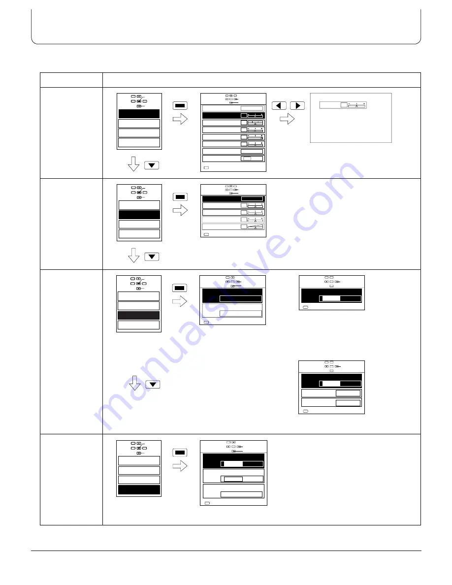
Menu Flowchart

If the MENU button is pressed, the Menu screen will be displayed.
If the MENU button is pressed once more while the menu screen is displayed, the Menu screen will be cleared.

Menu

On-Screen Indication

Picture

(Refer to 

page 24.)

Sound

(Refer to 

page 26.)

Signal

(Refer to 

page 27.)

Set up

(Refer to 

page 28.)

Picture

Sound

Signal

Set up

Access

Select

STR

Select

Adjust

Picture

Normal

Picture Mode

Manual W/B

White balance

Sharpness

Contrast

Brightness

Tint

Colour

Dynamic

Warm

Off

On

MENU

Exit

adjust

Colour

0

0

30

0

0

0

Picture

Sound

Signal

Set up

Access

Select

STR

Sound Mode

Normal

Treble

Balance

BBE sound

Bass

Sound

Normal

Exit

MENU

Select

Change

0

0

0

16

STR

Picture

Sound

Signal

Set up

Access

Select

Signal

Colour system

Auto

Field

Scan mode

Change
Select

Exit

MENU

Signal

Colour matrix

2

1

Change

Exit

MENU

V-Freq.  (Hz)

Sync on G

On

31

60

H-Freq.(kHz)

Off

Signal

Change

Exit

MENU

During Component mode

During RGB and PC modes

During AV(S-Video) mode

Picture

Sound

Signal

Set up

Access

Select

STR

Set up

COMPONENT/RGB IN

OSD Language

4:3

Panasonic Auto (4:3)

Just

RGB

English

Change
Select

Exit

MENU

Y/PB/PR

Summary of Contents for TC-42PD1FA

Page 1: ...Operating Instructions Wide Plasma Display TC 42PD1FA TQBC0211 INPUT ...

Page 2: ...ORTANT SAFETY NOTICE 3 Safety Precautions 4 Accessories 6 Accessories Supplied 6 Optional Accessories 6 Remote Control Batteries 7 Quick Start Guide 7 Set up 7 Connections 8 Plug in and switch on 9 Select the input signal 9 Basic Controls 10 Connections 11 Menu Flowchart 17 ASPECT Controls 18 PICTURE POS SIZE Controls 20 SURROUND Controls 22 PICTURE MODE Controls 23 Picture Menu 24 Sound Menu 26 S...

Page 3: ...ock do not remove cover No user serviceable parts inside Refer servicing to qualified service personnel 2 Do not remove the earthing pin on the power plug This apparatus is equipped with a three pin earthing type power plug This plug will only fit an earthing type power outlet This is a safety feature If you are unable to insert the plug into the outlet contact an electrician Do not defeat the pur...

Page 4: ...he rear When using the Wide Plasma Display The Wide Plasma Display is designed to operate on 220 240 V AC 50 60 Hz Do not cover the ventilation holes BDoing so may cause the Wide Plasma Display to overheat which can cause fire or damage to the Wide Plasma Display Do not stick any foreign objects into the Wide Plasma Display BDo not insert any metal or flammable objects into the ventilation holes o...

Page 5: ...gently using only the accessory cleaning cloth or a soft lint free cloth BIf the surface is particularly dirty wipe with a soft lint free cloth which has been soaked in pure water or water to which a small amount of neutral detergent has been added and then wipe it evenly with a dry cloth of the same type until the surface is dry BDo not scratch or hit the surface of the panel with fingernails or ...

Page 6: ...n book Remote Control Transmitter TNQE178 Batteries for the Remote Control Transmitter 2 R6 UM3 Size RCA BNC adaptor plug TJS1A4270 Cleaning Cloth TPEX006 Ferrite sleeve TSK1027 Guarantee Card BPedestal TY ST42PT1E BWall stand TY ST42PW1E BMobile stand TY ST42PF1E BWall hanging bracket vertical TY WK42PV1E BWall hanging bracket angled TY WK42PR1E BCeiling unit TY CE42PS1E BRS 232C Conversion cable...

Page 7: ...ma Display Always be sure to ask a qualified technician to carry out set up Example When using the pedestal to set up the Wide Plasma Display Note 1 Refer to the Installation Instructions supplied with the pedestal for details on assembling the pedestal R6 UM3 size 1 2 3 Press and slide off the battery cover Insert batteries note correct polarity and Replace the cover Quick Start Guide 1 2 3 Assem...

Page 8: ...cting equipment such as a VCR Connecting other types of equipment see pages 12 to 16 Example When connecting an S VIDEO VCR INPUT R L SPEAKERS 8 2 1 speakers Rear R S Video OUT Video OUT Audio OUT L R AUTO 75 HI Z OUT L IN VIDEO AUDIO S VIDEO AV VIDEO AUDIO 2 RCA Audio cables S VIDEO VCR Video input to S VIDEO socket Audio input to L R sockets Rear Ferrite sleeve Supplied less than 20 cm ...

Page 9: ...dicator not illuminated Stand by Red Power ON Green Select the input signal 1 Press the INPUT button to select the input video signal to be played back from equipment such as a VCR which has been connected to the Wide Plasma Display INPUT Power Indicator Power Switch INPUT INPUT 1 INPUT ...

Page 10: ... RGB PC input signal modes sequentially Sound mute On Off Volume Adjustment Push the Volume Up or Down Button to increase or decrease the sound volume level ASPECT AUTO button see page 18 N button see page 21 24 25 26 Surround button see page 22 PICTURE POS SIZE button see page 20 STORE button Cursor buttons to make selections and adjustments 30 60 90 0 Off Timer Button The Wide Plasma Display may...

Page 11: ... OUT Terminal see page 15 TUNER IN Terminal see page 16 REMOTE Terminal see page 16 SPEAKERS Terminals see page 8 AV IN Terminals see page 12 COMPONENT RGB IN Terminals see page 13 PC IN Terminals see page 14 SERIAL Terminal see page 15 To tighten To loosen Pull While pushing the knob Pull Cable fixing bands Secure any excess cables with bands as required ...

Page 12: ...udio cables Audio input to L R sockets Video input to S VIDEO socket S Video terminal pins layout S VIDEO Signal Connection Video Signal Connection Audio input to L R sockets Video input to BNC socket 2 RCA Audio cables VCR Video input to BNC socket RCA BNC adaptor plug Supplied Audio input to L R sockets 2 RCA Audio cables RCA Video cable Ferrite sleeve Supplied Ferrite sleeve Supplied Ferrite sl...

Page 13: ...8 2 Additional equipment and cables shown are not supplied with this set R Audio OUT L Y DVD Y PB PR OUT PB PR R L VD HD AUDIO Y G COMPONENT RGB IN PR R PB B AUDIO Y PB PR DVD Player Video input to Y PB PR sockets 3 RCA Video cables 2 RCA Audio cables Audio input to L R sockets The Wide Plasma Display rear terminals R L VD HD AUDIO Y G COMPONENT RGB IN PR R PB B AUDIO G B R VD HD Example of input ...

Page 14: ... PC 98 series computer which has a D sub 15P terminal or a Macintosh computer to the set 6 There is no need to use an adapter for computers with DOS V compatible D sub 15P terminal 7 The computer shown in the illustration is for example purposes only 8 Additional equipment and cables shown are not supplied with this set 9 The picture will become dark if a PC signal with a vertical scanning frequen...

Page 15: ...the TY SCP02RS1E RS 232C conversion cable optional accessory to connect the computer to the Wide Plasma Display 2 Refer to page 29 for details of the control method for the Wide Plasma Display 3 The computer shown is for example purposes only 4 Additional equipment and cables shown are not supplied with this set IN R AUTO 75 HI Z OUT L IN VIDEO AUDIO S VIDEO AV VIDEO Monitor Video Output Terminal ...

Page 16: ...h future compatible components How to connect the TUNER Input Terminal The TUNER Input terminal is reserved for use with future external compatible components SERIAL TUNER IN REMOTE PC IN The Wide Plasma Display rear terminals SERIAL TUNER IN REMOTE PC IN The Wide Plasma Display rear terminals ...

Page 17: ... Tint Colour Dynamic Warm Off On MENU Exit adjust Colour 0 0 30 0 0 0 Picture Sound Signal Set up Access Select STR Sound Mode Normal Treble Balance BBE sound Bass Sound Normal Exit MENU Select Change 0 0 0 16 STR Picture Sound Signal Set up Access Select Signal Colour system Auto Field Scan mode Change Select Exit MENU Signal Colour matrix 2 1 Change Exit MENU V Freq Hz Sync on G On 31 60 H Freq ...

Page 18: ...mponent input signal mode the mode switches between Zoom1 and 16 9 only 3 When an S1 signal is being received during S Video input signal mode the mode is set to 16 9 mode 4 When a 1080i signal is being received the mode is set to 16 9 mode and switching is not possible 5 The aspect mode is memorised separately for different input signal formats NTSC PAL SECAM 525p RGB and PC 525p includes 525i an...

Page 19: ...een which is cut in Zoom1 mode so that this section still remains visible 16 9 16 9 will display the picture at its maximum size but with slight elongation Just Just mode will display a 4 3 picture at maximum size but with aspect correction applied to the centre of the screen so that elongation is only apparent at the left and right edges of the screen The size of the picture will depend on the or...

Page 20: ...The vertical position cannot be changed when Size 1 and Size 2 have been selected in 4 3 mode and when Size 1 has been selected in 16 9 mode In addition the vertical position cannot be changed when 1080i signals are being input 3 Adjustment details are memorised separately for different input signal formats NTSC PAL SECAM 525p 480p 1080i 525i and 625i 4 If a Cue or Rew signal from a VCR or DVD pla...

Page 21: ...to the factory setting level Mode Picture H pos When the Position Left I button is pressed When the Position Right H button is pressed V pos When the Position Left I button is pressed When the Position Right H button is pressed H size When the Position Left I button is pressed When the Position Right H button is pressed V size When the Position Left I button is pressed When the Position Right H bu...

Page 22: ...as if you were at a concert hall or cinema The surround setting switches on and off each time the SURROUND button is pressed Note 1 The surround settings are memorised separately for each input terminal AV COMPONENT RGB and PC PLASMA DISPLAY INPUT PC MANUAL ASPECT AUTO PICTURE MODE MENU N STR PICTURE POS SIZE 1 On Off Surround On ...

Page 23: ...re memorised separately for five types of input signal format NTSC PAL SECAM 1080i and RGB PC NTSC includes 525i and 525p 480p signals and PAL includes 625i signals Normal For viewing in normal evening lighting environments This menu selects normal levels of Brightness and Contrast Dynamic For viewing in brighter environments This menu selects a higher than normal levels of Brightness and Contrast...

Page 24: ...The Tint setting can be adjusted for NTSC signal only 2 Colour Tint and Sharpness settings cannot be adjusted during RGB and PC input signal modes 3 If the Manual W B setting is changed to ON and the Position Down G button is pressed the Manual W B menu will be displayed Refer to page 25 4 The adjustment range values should be used as an adjustment reference Picture Mode Function Normal For viewin...

Page 25: ...30 30 Adjusts the white balance for light red areas W B High B 30 30 Adjusts the white balance for light blue areas W B Low R 30 30 Adjusts the white balance for dark red areas W B Low B 30 30 Adjusts the white balance for dark blue areas Item Adjustment value for cold white balance Adjustment value for warm white balance W B High R 5 10 W B High B 10 5 W B Low R 0 0 W B Low B 0 0 1 2 Select Adjus...

Page 26: ...er than the Balance value are memorised separately for each Sound Mode Normal Music Speech 3 The adjustment range values should be used as an adjustment reference Sound Mode Function Normal Same sound as the input signal Music Bass and Treble is set to optimum level for music Speech Bass and Treble is set to optimum level for speech Item Effect Adjustment range Bass 15 15 Treble 15 15 Balance 30 3...

Page 27: ...g a normal image select the Field If the recording mode used for a device such as a digital video camera is Frame select the Frame to obtain a higher quality playback image Mode Function Colour matrix If the output signals from the source connected to the COMPONENT RGB input terminals are in 525p 480p format the colours in the images from this source will be set to their natural colours MENU STR P...

Page 28: ...lect the Set up Menu by pushing the Position Up F or Down G Button and Access the Set up Menu by pushing the STR Button 3 Select the required mode by pushing the Position Up F or Down G buttons and set appropriate function by pushing the Position Left I or Right H buttons Mode Function COMPONENT RGB IN Select to match the signals from the source connected to the COMPONENT RGB input terminals Y PB ...

Page 29: ...es SERIAL REMOTE 7 8 9 6 1 2 3 4 5 TXD A RXD B GND C A B C SERIAL terminal 2 5 mm 3 pin female RS 232C Conversion cable 2 5 mm 3 pin male Pin Layout for RS 232C Conversion cable D sub 9 pin female Basic format for control data The transmission of control data from the computer starts with an STX signal followed by the command the parameters and lastly an ETX signal in that order If there are no pa...

Page 30: ...System Refer to page 27 Image too bright Normal Sound A video signal has been connected to the AV output terminal by mistake The input becomes high impedance and the image becomes too bright Connect video signals to the video input terminal Symptoms Checks Some parts of the screen do not light up The plasma display panel is manufactured using an extremely high level of precision technology however...

Page 31: ...quency 15 6 50 kHz AV VIDEO IN BNC 1 0 Vp p 75 Ω with 75 Ω or high impedance auto select S VIDEO IN Y 1 Vp p 75 Ω C 0 286 Vp p 75 Ω Mini DIN 4 pin AUDIO IN L R 0 5 Vrms RCA pin jack 2 VIDEO OUT BNC 1 0 Vp p 75 Ω bridge output COMPONENT RGB Y G 1 0 Vp p including synchronisation PB B 0 35 Vp p PR R 0 35 Vp p HD 1 0 5 0 Vp p VD 1 0 5 0 Vp p AUDIO IN L R 0 5 Vrms RCA pin jack 2 PC VIDEO High density ...

Page 32: ... PC 98 is a trademark of NEC Corporation All other trademarks mentioned in this manual are the property of their respective owners Sound BBE has been created under license from BBE Sound Incorporated is a registered trademark of BBE Sound Incorporated Accessories Supplied Optional Accessories Dimensions W D H INPUT 1030mm 633 5mm 1193mm 89mm Weight Mass Matsushita Electric Industrial Co Ltd Centra...

Reviews: