- 17 -
TC-20G12P / TC-29G12P / TC-29G12PU
Service Adjustments and Calibrations
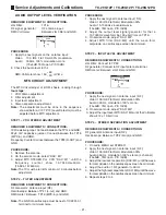
INITIAL DATA RECORDING IN THE MEMORY (EEPROM)
1. Initial data must be recording before IC memory
installation in the circuit board.
2. The data of A0 address, is individual for each model.
The data of A2 and A4 are common to all models.
DATA MEMORY ON THE SCREEN
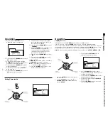
HOW TO ENTER INTO SERVICE MODE:
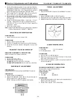
1. Switch to CATV and set the 124 CATV channel.
2. Adjust minimum volume with the
Vol(_)
button.
3. Adjust
SLEEP
function to 30 and press the button
Vol(_)
on the TV panel.
4. To alter among CHQs (B0
→
C0
→
S0
→
M0), press
POWER
.
5. To alter among DACs (B0
→
B1... and C0
→
C1...),
press
CH(+)
or
CH(_)
and to alter the values press
VOL(+)
or
Vol(_)
.
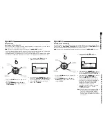
6. To get access to contents of directions of the memory
address shows bellow, set DAC S 0 and press
MUTE
button on the remote control, for about 3 sec.
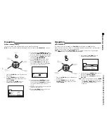
TO EXIT SERVICE MODE:
1. Press
ACTION
and
POWER
button simultaneously,
on the TV panel , for about 3 sec.
RESET:
Press simultaneously
ACTION
and
POWER
button for about 5 sec. All programming done
(clock, color, color system through channels or
signal ) will be cover for the original factory
adjustments.
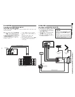
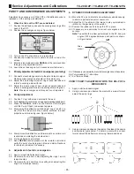
SERVICE MODE
Address A0
Address A2
Address A4
(AT SCREEN)
Address Table
A0, A2 and A4
Address Column
(First line) 0 - F
Address Line
(First Column) 0 - F
0 1 2
Summary of Contents for TC-29G12P
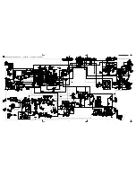
Page 27: ...27 TC 20G12P TC 29G12P TC 29G12PU Main Board Schematic Diagram TC 20G12P TC 29G12P TC 29G12PU...
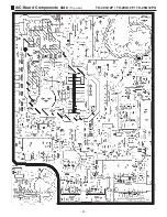
Page 31: ...31 TC 20G12P TC 29G12P TC 29G12PU A C Board Components side Top view...
Page 32: ...32 TC 20G12P TC 29G12P TC 29G12PU A C Board Foil side Bottom view...
Page 33: ...33 TC 29G12P TC 29G12PU Cabinet Parts Location...
Page 41: ......
Page 42: ...Panasonic do Brasil Ltda CS GROUP TECHNICAL SUPPORT...


