background image

11

Step 3

RQT74

92

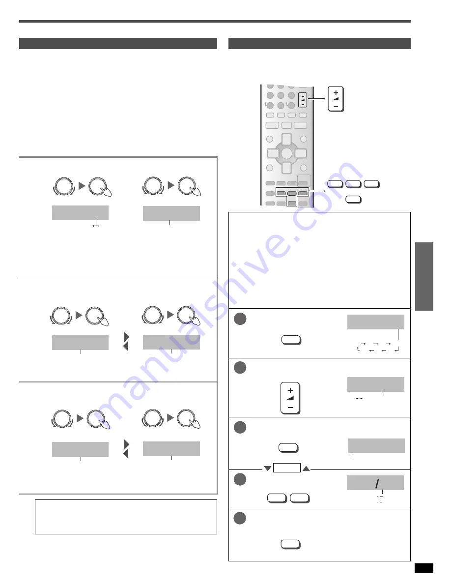
Adjusting speaker output level

Adjust the level of the other speakers based on the output of the front
speakers. (Output is only from the speakers selected in the SPEAKERS
settings. Adjust the volume of the front speakers with [VOLUME].) 

2. Select.

3. Select the speakers.

C (center), RS (right surround), SB (surround back) and LS (left
surround) can be adjusted between –10 dB and +10 dB, with 0 being the
level of the front speakers. 
Adjust center, surround and surround back output to the same apparent
level of the front speakers. 

For SW (subwoofer), you can select “MIN” for minimum output, a level
between 1 and 19, or “MAX” for maximum output. Adjust subwoofer
output so it is balanced with the front speakers. Subwoofer output is
easily influenced by the source. You can also change its level while
playing something for better effect (

á

 page 19).

Preparation: Press [SPEAKERS A] to turn on SPEAKERS A. 

(On the main unit)

2. Select the input 

position.

3. Change the setting.

Output the signal.

Adjust the main volume.

2. Select the input 

position.

3. Change the setting.

Select the speaker channel.

Adjust the level.

c

For more detailed information on settings refer to 
“Advanced setup” on page 22.

Stop the test signal.

VOLUME

+

q

w

LEVEL

TEST

u

/

t y

/

i

4

5

6

7

8

9

DISC

0

10

>

=

VOLUME

-/--

DIRECT TUNING

TUNER/BAND

MUTING

h

q

g

TOP MENU

MENU

DIRECT

NAVIGATOR

PLAY

LIST

DISPLAY

RETURN

TV VOL –

TV VOL +

HELP

TV/AV

DVD RECORDER

DVD/HDD

SUBWOOFER

+

q

w

CENTER

FOCUS

MULTI

REAR

LEVEL

EFFECT

STEREO/

DTS

DIMMER

TEST

ENTER

q

r

w

e

INPUT SELECTOR

INPUT SELECTOR

SUBW YES

YES

NO

INPUT SELECTOR

INPUT SELECTOR

LCR  S  SB

LCR S SB, 
L_R S SB,
LCR S _ _, 
L_R S _ _, 
LCR _ _ _, 
L_R _ _ _

INPUT SELECTOR

INPUT SELECTOR

TV

TV, DVR, DVD, CD

INPUT SELECTOR

INPUT SELECTOR

OPT    1

OPT 1, OPT 2,
COAX 1, COAX 2

1

TEST

TEST    L

L

R

C

RS

SB

LS

SW

Two seconds each.

2

VOLUME

VOL- 50dB

--dB (minimum)

0 dB (maximum)

INPUT SELECTOR

INPUT SELECTOR

TV

TV, DVR, DVD, CD

INPUT SELECTOR

INPUT SELECTOR

AUTO

AUTO, ANALOG,
DIGITAL, PCM FIX

3

LEVEL

C        0dB

C, RS, SB, LS, SW

4

+

q

w

5

TEST

C     - 4dB

-10 dB

+10 dB

       MIN, 1

19, MAX

Repeat

Summary of Contents for SAXR50 - DIGITAL A/V RECEIVER

Page 1: ...e control 3 Control guide 14 The radio 16 RDS broadcasts 18 Audio settings 19 Other functions 21 Making a recording 21 Advanced setup 22 Specifications 23 Troubleshooting guide Back cover Maintenance Back cover Before use Step 1 Home Theater connections 4 DVD player Speakers TV or monitor AC mains lead Step 2 Other connections 6 DVD recorder VCR CD recorder TV or monitor Tape deck Cable box or sat...

Page 2: ...the fuse cover the plug must not be used until a replacement cover is obtained A replacement fuse cover can be purchased from your local dealer CAUTION IF THE FITTED MOULDED PLUG IS UNSUITABLE FOR THE SOCKET OUTLET IN YOUR HOME THEN THE FUSE SHOULD BE REMOVED AND THE PLUG CUT OFF AND DISPOSED OF SAFELY THERE IS A DANGER OF SEVERE ELECTRICAL SHOCK IF THE CUT OFF PLUG IS INSERTED INTO ANY 13 AMPERE ...

Page 3: ...nly For Republic of Ireland please use the Customer Care Centre number listed above for all enquiries For all other product related enquiries please use the Customer Care Centre numbers listed above For Australia and New Zealand K2CJ2DA00010 For continental Europe K2CQ2CA00002 For the United Kingdom VJA0733 For the United Kingdom K1YZ02000013 For Australia and New Zealand RFE0014 Batteries Use CAU...

Page 4: ...akers should be placed at approximately the same distance from the seating area The angles in the diagram are approximate White L Red R 75Ω LOOP EXT FM ANT AM ANT IN CD L R REC OUT PLAY IN TAPE LOOP ANT GND IN TV DVR VCR1 OUT IN OUT OPTICAL TV IN OPTICAL1 OPTICAL2 DVR IN COAXIAL2 CD IN OUT SUBWOOFER OUT IN DVR VCR1 MONITOR OUT TV MONITOR OU Y PB P IN IN TV DVD D S VIDEO IN DVD CENTER SUBWOOFER SUR...

Page 5: ...result in unnatural bass Cable Speaker terminals Twist the wire FRONT A Other terminals Note Do not short circuit Peripheral equipment and cables sold separately unless otherwise indicated To connect equipment refer to the appropriate operating instructions Front right Front left Surround right Surround left Surround back Speakers Speaker Impedance Front A 6 16 Ω A and B 6 16 Ω Center 6 16 Ω Surro...

Page 6: ... OUT PLAY IN TAPE LOOP ANT GND IN TV OUT OPTICAL TV IN OPTICAL1 COAXIAL2 CD IN OUT SUBWOOFER MONITOR OUT TV MONITOR OUT Y PB PR IN IN IN TV DVD DVR VCR1 Y PB PR Y PB PR TV IN S VIDEO DVD IN COMPONENT VIDEO CENTER SUBWOOFER SURROUND FRONT DVD DVD 6CH COAXIAL1 IN DVD MONITOR OUT IN TV R FRON DVD IN DVR VCR1 OUT IN AUDIO VIDEO OPTICAL2 DVR IN OUT IN DVR VCR1 DIGITAL TV DIGITAL AUDIO OUT VIDEO OUT VID...

Page 7: ...VD VIDEO MONITOR OUT IN TV R L FRONT A Class 2 Wiring DVD IN TV MONITOR OUT Y PB PR IN Y PB PR TV IN S VIDEO TV MONITOR OUT COMPONENT VIDEO S VIDEO OUT S VIDEO IN COMPONENT VIDEO OUT Y COMPONENT VIDEO OUT PB COMPONENT VIDEO OUT PR COMPONENT VIDEO IN PR COMPONENT VIDEO IN PB COMPONENT VIDEO IN Y LOOP ANT GND DVR VCR1 OUT IN OUT OPTICAL TV IN OPTICAL1 OPTICAL2 DVR IN COAXIAL2 CD IN OUT SUBWOOFER OUT...

Page 8: ...R IN COAXIAL2 CD IN OUT SUBWOOFER OUT IN DVR VCR1 MONITOR OUT TV MONITOR OUT Y PB PR IN IN IN TV DVD DVR VCR1 Y PB PR Y PB PR TV IN S VIDEO DVD IN COMPONENT VIDEO CENTER SUBWOOFER SURROUND FRONT DVD DVD 6CH AUDIO COAXIAL1 IN DVD VIDEO MONITOR OUT IN TV R FRON DVD IN OUT OPTICAL DIGITAL DIGITAL IN 75Ω LOOP EXT FM ANT AM ANT IN CD L R LOOP ANT GND IN TV DVR VCR1 OUT IN OUT OPTICAL TV IN OPTICAL1 OPT...

Page 9: ...xial cable For best resistance to interference use 75 Ω coaxial cable 300 Ω feeder wire 75 Ω coaxial cable Antenna plug included To connect a 75 Ω coaxial cable 75 Ω coaxial cable Remove a piece of the outer vinyl insulator Remove the lead wire and clamp it with the plastic bar 10 mm 7 mm Plastic bar Install the coaxial cable Clamp the cable conductor and wind it on so that it does not contact any...

Page 10: ...E Input mode 1 Select This unit automatically detects whether input is digital or analogue but you can fix the input mode AUTO Automatically detects the input signal and plays ANALOG Fixes the input signal to analogue and plays DIGITAL Fixes the input signal to digital and plays PCM FIX Fixes the input signal to PCM and plays To finish settings Note regarding PCM FIX mode In rare cases the unit ma...

Page 11: ...it 2 Select the input position 3 Change the setting Output the signal Adjust the main volume 2 Select the input position 3 Change the setting Select the speaker channel Adjust the level c For more detailed information on settings refer to Advanced setup on page 22 Stop the test signal VOLUME q w LEVEL TEST u t y i 4 5 6 7 8 9 DISC 0 10 VOLUME DIRECT TUNING TUNER BAND MUTING h q g TOP MENU MENU DIR...

Page 12: ...ed to enhance vocals SPORTS Enjoy a feeling like being at a live sporting event Adjust the volume JAZZ Recreates natural sound ambience and direction MUSICAL Enjoy a feeling like being at a live musical performance DANCE Enjoy a dance hall like audio effect GAME Enjoy games with greater audio impact PARTY This mode uses the front and surround speakers so that sound is in stereo regardless of the d...

Page 13: ... 6 1CH DECODING is on 1 19 MAX Output is only from the speakers selected in the SPEAKERS settings To adjust SFC effect Adjust the effect SFC effect can be adjusted between EFFECT 1 minimum and EFFECT 10 maximum The factory setting is EFFECT 5 for each mode Listening to multi channel sources in stereo 2CH MIX mode When multi channel sources are played in this mode the sounds intended for the other ...

Page 14: ...rn the speakers off when using the headphones Display SPEAKERS Speaker indicators Sound is output from speakers connected to the front A surround and center terminals Sound is output only from speakers connected to the front B terminals Sound is output from speakers connected to the front A and B terminals TUNED ST MONO Radio indicators TUNED A station is tuned ST A stereo FM broadcast is tuned Fl...

Page 15: ...nable selection of radio stations by frequency 10 To enter two digit channels TUNER BAND Change the input mode and remote control mode to TUNER For switching between FM and AM 1 CH 2 For selecting preset radio channels 4 3 VOLUME To adjust the volume HELP Displays help messages Press if an error message appears A message offering a possible solution scrolls across the display MUTING To mute the vo...

Page 16: ... Select TUNER 2 Select AM ALLOC 3 Select 9 kHz or 10 kHz For your reference Improving reception DVD players can interfere with radio reception Turn the DVD player off or move it further away from the antennas if this occurs Beat proof mode Changing these settings also changes the A D attenuator settings which are linked á page 20 To finish settings 1 Press MULTI CONTROL several times to select EXI...

Page 17: ...etting 1 Select 2 Select 3 Select the channel Preparation Set the station signal you want to set as a preset Preset the stations one at a time FM stations can also be preset in the MONO mode To continue presetting press TUNE 2 or 1 to tune another station from step For your reference Even if the AC mains lead is disconnected from the household mains socket the stations remain in memory for approxi...

Page 18: ...asts PTY displays NEWS News FINANCE Finance AFFAIRS Current affairs CHILDREN Children INFO Information SOCIAL A Social affairs SPORT Sport RELIGION Religion EDUCATE Education PHONE IN Phone in DRAMA Drama TRAVEL Travel CULTURE Culture LEISURE Leisure SCIENCE Science JAZZ Jazz music VARIED Varied COUNTRY Country music POP M Pop music NATIONAL National music ROCK M Rock music OLDIES Oldies M O R M M...

Page 19: ... is selected Press and hold at the same time for 2 seconds To cancel perform the same operation again AUTO is displayed In rare cases the unit may have trouble recognizing the digital signals on discs With DTS the signals may not be recognized at all Engage the DTS FIX mode if this occurs When DTS FIX mode is on the unit cannot process other signals This may cause noise to be output Turn the setti...

Page 20: ...DARD The level recommended by the producer of the software for household viewing MAX The maximum allowable compression recommended for night viewing 1 Select 2 Select 3 Select To finish settings A D attenuator 1 Select 2 Select 3 Select 1 Press MULTI CONTROL several times to select EXIT 2 Press INPUT SELECTOR Turn the A D attenuator on if OVERFLOW lights frequently when using 2 channel analogue in...

Page 21: ... instructions for details on how to prepare it for recording Note With a tape deck you can record any analogue source except TAPE With a DVD recorder VCR you can record any analogue source except TAPE and DVR VCR1 With digital recording equipment you can record any digital source without copy protection When you select DVD ANALOG 6CH mode only sound from the front left and right channels is record...

Page 22: ...ed so that sound reaches the listener at the same time You can select distances between 1 0 and 10 0 m at 0 1 meter intervals 1 Select 2 Select the speaker 3 Change the setting FILTER 1 Select 2 Change the setting Change the cut off for bass output from the front speakers If you set the front speakers to SMALL the filter is set to 100 Hz Raise the cut off if the bass from the front speakers is uns...

Page 23: ...output impedance 75 Ω unbalanced S Video Input TV DVD DVR VCR1 Output TV MONITOR Component Video Input TV DVD Output TV MONITOR n GENERAL Power supply AC 230 240 V 50 Hz Power consumption 135W Dimensions W x H x D 430 x 83 x 376 mm Mass 4 2 kg Notes 1 Specifications are subject to change without notice Mass and dimensions are approximate 2 Total harmonic distortion is measured by the digital spect...

Page 24: ...lt your dealer Sound is not heard from the center surround or subwoofer speakers Ensure the SPEAKERS settings for your speakers are correct Turn 2CH MIX off The source may be stereo Change the sound mode 10 22 13 12 Sound is not heard from the surround back speaker Ensure the SPEAKERS settings for your speakers are correct Turn 6 1CH DECODING mode on 10 22 12 Cannot use Dolby Pro Logic Ⅱ DTS NEO 6...

Reviews: