The laser diode in the traverse deck (optical pickup) may break
down due to potential difference caused by static electricity of
clothes or human body.
So, be careful of electrostatic breakdown during repair of the
traverse deck (optical pickup).
●
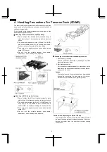
Handling of CD traverse deck (optical pickup)
1. Do not subject the traverse deck (optical pickup) to
static electricity as it is extremely sensitive to electrical
shock.
2. The short land between the No.4 (LD) and No.5 (GND)
pins on the flexible board (FFC) is shorted with a solder
build-up to prevent damage to the laser diode.
3. Take care not to apply excessive stress to the flexible
board (FPC board).
4. Do
not
turn
the
variable
resistor
(laser
power
adjustment). It has already been adjusted.
●
Handling of MD Unit (optical pickup)
1. Do not subject the MD unit (optical pickup) to static
electricity as it is extramely sensitive to electrical shock.
2. The short land between the No.25 (LD-GND) and No.
24 (LD) pins on the flexible board is shorted with a
solder builder up to prevent damage to the laser diode.
3. Take care not to apply excessive stress to the flexible
board (FFC).
4. Do
not
turn
the
variable
resistor
(laser
power
adjustment). It has already been adjusted..
●
Grounding for electrostatic breakdown prevention
1. Human body grounding
Use the anti-static wrist strap to discharge the static
electricity from your body.
2. Work table grounding
Put a conductive material (sheet) or steel sheet on the
area where the traverse deck (optical pickup) is placed,
and ground the sheet.
Caution :
The static electricity of your clothes will not be grounded
through the wrist strap. So, take care not to let your
clothes touch the traverse deck (optical pickup).
Caution when Replacing the Optical Pickup :
The traverse has a short point shorted with solder to protect
the laser diode against electrostatics breakdown. Be sure to
remove the solder from the short point before making
connections.
4 Handling Precautions For Traverse Deck (CD/MD)
4
SA-PM30MD
Summary of Contents for SA-PM30MD
Page 6: ...6 Caution for AC Mains Lead 6 SA PM30MD ...
Page 7: ...7 Operation Procedures 7 SA PM30MD ...
Page 8: ...8 SA PM30MD ...
Page 74: ...16 Wiring Connection Diagram 74 SA PM30MD ...
Page 75: ...17 Troubleshooting Guide 75 SA PM30MD ...
Page 76: ...76 SA PM30MD ...
Page 77: ...77 SA PM30MD ...
Page 78: ...78 SA PM30MD ...
Page 79: ...79 SA PM30MD ...
Page 80: ...80 SA PM30MD ...
Page 81: ...81 SA PM30MD ...
Page 82: ...82 SA PM30MD ...
Page 84: ...18 1 1 Deck Mechanism Parts Location 18 1 Deck Mechanism RAA4106 84 SA PM30MD ...
Page 86: ...18 2 MD Mechanism 18 2 1 MD Mechanism Parts location 86 SA PM30MD ...
Page 88: ...18 3 CD Loading Mechanism 18 3 1 CD Loading Mechanism Parts Location 88 SA PM30MD ...
Page 90: ...18 4 1 Cabinet Parts Location 18 4 Cabinet 90 SA PM30MD ...
Page 91: ...91 SA PM30MD ...


