Measurement condition
•
Record timer : OFF
•
Make sure head, capstan and pressure roller are clean.
•
Judgeable room temperature 20 ± 5 °C (68 ± 9 °F)
Measuring instrument
•
EVM (Electronic Voltmeter)
•
Digital frequency counter
Note :
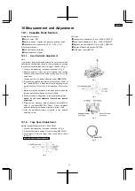
If you wish to readjust the head azimuth, be sure to adjust with
adhering the casette tape closely to the mechanism by pushing
the cebter of cassette tape with your finger. (Shown in Fig. 1)
1. Connect the measuring instrument as shown in Fig. 2.
2. Replace azimuth screws for both forward and reverse
direction after removing the screw-locking bond left on the
head base.
(Supply part No. of azimath adjusting screw: RHD17015)
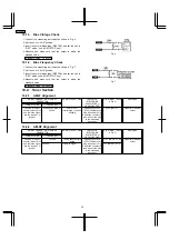
3. Playback the azimuth adjustment portion(8kHz, -20dB) of
test tape(QZZCFM). Adjust the azimuth adjusting screw
until the outputs of the L/Rch are maximized. (Refer to Fig.
3)
Make sure that the difference in the peak level between the
left and right channels does not exceed 0.5dB.
4. Perform the same adjustment in reverse playback mode.
Check of the level difference forward and reverse
directions
5. Playback the playback gain adjustment portion(315Hz,
0dB) of test tape(QZZCFM). Check if level difference
between forward and reverse direction is within 1.5dB.
6. After the adjustment, apply screwlock to the azimuth
adjusting screw.
Normal speed (Standard value : 3000 ± 90Hz)
1. Connect the measuring instrument as shown in Fig. 4.
2. Playback the middle portion of the test tape (QZZCWAT).
3. Adjust motor VR for the output value shown below. (Refer
to Fig. 5)
Adjustment target : 3000 ± 40Hz
Fig. 4
Test tape
•
Headazimuth adjustment (8 kHz, -20 dB); QZZCFM
•
Tape speed adjustment (3 kHz, -10 dB); QZZCWAT
•
Playback gain adjustment (315 Hz, 0 dB); QZZCFM
•
Normal reference blank tape; QZZCRA
•
CrO2 blank tape; QZZCRX
Fig. 1
Fig. 2
Fig. 3
Fig. 5
10 Measurement and Adjustment
10.1. Cassette Deck Section
10.1.1. Head Azimuth Adjustment
10.1.2. Tape Speed Adjustment
21
SA-PM30MD
Summary of Contents for SA-PM30MD
Page 6: ...6 Caution for AC Mains Lead 6 SA PM30MD ...
Page 7: ...7 Operation Procedures 7 SA PM30MD ...
Page 8: ...8 SA PM30MD ...
Page 74: ...16 Wiring Connection Diagram 74 SA PM30MD ...
Page 75: ...17 Troubleshooting Guide 75 SA PM30MD ...
Page 76: ...76 SA PM30MD ...
Page 77: ...77 SA PM30MD ...
Page 78: ...78 SA PM30MD ...
Page 79: ...79 SA PM30MD ...
Page 80: ...80 SA PM30MD ...
Page 81: ...81 SA PM30MD ...
Page 82: ...82 SA PM30MD ...
Page 84: ...18 1 1 Deck Mechanism Parts Location 18 1 Deck Mechanism RAA4106 84 SA PM30MD ...
Page 86: ...18 2 MD Mechanism 18 2 1 MD Mechanism Parts location 86 SA PM30MD ...
Page 88: ...18 3 CD Loading Mechanism 18 3 1 CD Loading Mechanism Parts Location 88 SA PM30MD ...
Page 90: ...18 4 1 Cabinet Parts Location 18 4 Cabinet 90 SA PM30MD ...
Page 91: ...91 SA PM30MD ...

