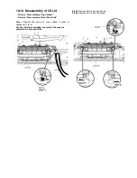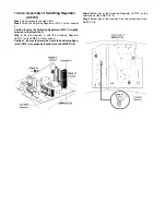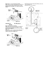
Step 3
Remove 1 screw at Rectifier Diode (D5801).
Step 4
Remove the Rectifier Diode (D5801) from the SMPS
P.C.B..
Caution: Avoid touching the Heatsink B due to its high
temperature after prolonged use. Touching it may lead to
injuries.
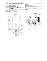
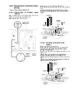
10.24.2. Assembly of Rectifier Diode
(D5801)
Step 1
Apply grease to the Heatsink B.
Step 2
Screw the Rectifier Diode (D5801) to the Heatsink B.
Caution: Ensure the Rectifier Diode (D5801) is tightly
screwed to the Heatsink B.
Step 3
Fix the Heatsink B with Rectifier Diode (D5801) on the
SMPS P.C.B..
Caution: Ensure pins of the Rectifier Diode (D5801) are
properly inserted into the SMPS P.C.B..
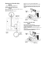
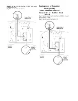
Step 4
Solder pins of the Rectifier Diode (D5801) on the solder
side of the SMPS P.C.B..
Step 5
Solder pins of the Heatsink B.
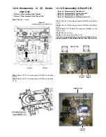
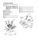
10.25. Disassembly of CD Interface P.C.B.
Refer to “Disassembly of Top Cabinet”.
Refer to “Disassembly of Front Panel Unit”.
Refer
to
“Disassembly
of
CD
Mechanism
Unit
(BRS11C)”.
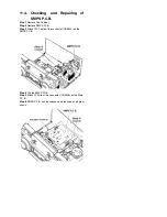
Step 1
Remove 3 screws.
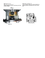
Step 2
Desolder pins of the motor (M7301).
Step 3
Desolder pins of the motor (M7302).
Summary of Contents for SA-MAX500LMK
Page 14: ...5 General Introduction 5 1 Media Information ...
Page 26: ...9 1 2 Main P C B Front Side Fig 2 Main P C B Front Side Regulator Circuit IC2014 ...
Page 27: ...Fig 3 Main P C B Back Side ...
Page 30: ...9 3 D Amp IC Operation Control MAX500 ...
Page 34: ......
Page 36: ...10 3 Main Components and P C B Locations SMPS P C B ...
Page 84: ...14 3 FL Display Circuit MAX500 ...
Page 85: ...14 4 Volume Circuit MAX500 ...
Page 86: ...MAX500 14 5 Control USB Circuit ...
Page 87: ...14 7 Remote Sensor MAX500 ...
Page 88: ...MAX500 ...
Page 89: ... Jog Board MAX500 ...
Page 90: ...Internal Fan MAX500 ...
Page 124: ...17 1 3 Mechanical Replacement Part List ...

