


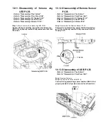

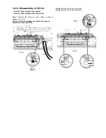


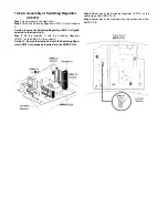


10.6. Disassembly
of
FL
Display
P.C.B.
s
Refer to “Disassembly of Top Cabinet”.
s
Refer to “Disassembly of Front Panel Unit”.
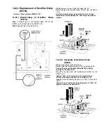
Step 1
Remove 6 screws.
Step 2
Release 4 catches.
Step 3
Lift up the FL Display P.C.B..
Step 4
Detach 30P FFC at a connector (CN6000) on the FL
Display P.C.B..
Caution: During assembling, ensure that the FL Display
P.C.B. is properly located and fully catched onto Front
Panel Unit.
CN6000
Summary of Contents for SA-MAX500LMK
Page 14: ...5 General Introduction 5 1 Media Information ...
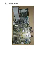
Page 26: ...9 1 2 Main P C B Front Side Fig 2 Main P C B Front Side Regulator Circuit IC2014 ...
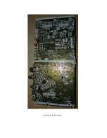
Page 27: ...Fig 3 Main P C B Back Side ...
Page 30: ...9 3 D Amp IC Operation Control MAX500 ...
Page 34: ......
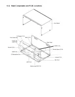
Page 36: ...10 3 Main Components and P C B Locations SMPS P C B ...
Page 84: ...14 3 FL Display Circuit MAX500 ...
Page 85: ...14 4 Volume Circuit MAX500 ...
Page 86: ...MAX500 14 5 Control USB Circuit ...
Page 87: ...14 7 Remote Sensor MAX500 ...
Page 88: ...MAX500 ...
Page 89: ... Jog Board MAX500 ...
Page 90: ...Internal Fan MAX500 ...
Page 124: ...17 1 3 Mechanical Replacement Part List ...


