


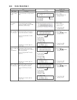


8.2.2.
Doctor Mode Table 2
FL Display
Key Operation
Front Key
Item
Description
Mode Name
Volume Setting
Check
FL Display
Check
To check the volume setting of a main
unit.
To check the FL segment display
All segment will light up while all LED
blink at 0.5s,intervals.(if any)
In Doctor Mode :
1. Press [7], [8], [9] button
on remote control.
In Doctor mode :
1. Press [1] button on
remote control.
Press [7]: VOL50
Press [8]: VOL35
Press [9]: VOL0
Vo lume
In this mode, the tray will open &
close.
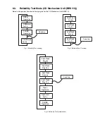
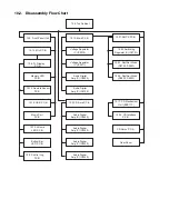
Note: Refer to Section 8.3 Fig 1 for
process flow .
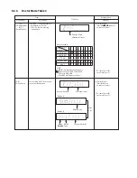
The counter will
increment by one .
When reach 9999
will change to 0000
Cancellation Display
BRS11C Reliability
Test (Loading)
To determine CD Mechanism Unit
(BRS11C) Open/Close operation.
Note: Refer to Section 8.3 Fig 2. for
process flow .
The counter will
increment by one .
When reach 9999
will change to 0000
Cancellation Display
BRS11C Reliability
Test (Traverse)
Test
To determine CD Mechanism BRS11C
Access Inner & Outer disc operation.
Note: Refer to Section 8.3 Fig 3. for
process flow .
The counter will
increment by one .
When reach 9999
will change to 0000
Cancellation Display
BRS11C Reliability
(Combination)
In this mode,ensure the CD is in the
main unit.
To determine CD Mechanism Unit
(BRS11C) Open/Close & Access Inner &
Outer Disc Operation.
In this mode,ensure the CD is in the
main unit.
In Doctor Mode :
1. Press [10] [2] [1] button
on remote control.
2. To cancel, press [0]
on remote control.
In Doctor Mode :
1. Press [10] [1] [2] button
on remote control.
2. To cancel, press [0]
on remote control.
2. To cancel, press [0 ]
on remote control.
In Doctor Mode :
1. Press [10] [1] [5] button
on remote control.
2. To cancel, press [0]
on remote control .
Summary of Contents for SA-MAX500LMK
Page 14: ...5 General Introduction 5 1 Media Information ...
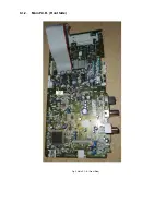
Page 26: ...9 1 2 Main P C B Front Side Fig 2 Main P C B Front Side Regulator Circuit IC2014 ...
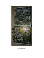
Page 27: ...Fig 3 Main P C B Back Side ...
Page 30: ...9 3 D Amp IC Operation Control MAX500 ...
Page 34: ......
Page 36: ...10 3 Main Components and P C B Locations SMPS P C B ...
Page 84: ...14 3 FL Display Circuit MAX500 ...
Page 85: ...14 4 Volume Circuit MAX500 ...
Page 86: ...MAX500 14 5 Control USB Circuit ...
Page 87: ...14 7 Remote Sensor MAX500 ...
Page 88: ...MAX500 ...
Page 89: ... Jog Board MAX500 ...
Page 90: ...Internal Fan MAX500 ...
Page 124: ...17 1 3 Mechanical Replacement Part List ...


