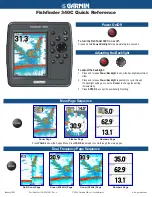
17.4. Panel Diagram
SA-
AK450P/PC PANEL DIAGRAM
TO TRANSFORMER
TO MAIN
(2/2)
TO MAIN
(2/2)
TO MAIN
(1/2)
TO MAIN
(2/2)
TO MAIN
(1/2)
H6555 CN5951
1
H6555 CN5951
2
CN6601 CN2806
12
CN6601 CN2806
2
CN6601 CN2806
5
CN6601 CN2806
20
CN6601 CN2806
22
CN6601 CN2806
8
CN6601 CN2806
25
CN6601 CN2806
27
CN6601 CN2806
9
CN6601 CN2806
16
CN6601 CN2806
7
CN6601 CN2806
17
JW6601 JW6002
3
JW6601 JW6002
7
JW6601 JW6002
10
JW6601 JW6002
9
JW6601 JW6002
8
JW6601 JW6002
2
JW6601 JW6002
4
CN6601 CN2806
3
CN6601 CN2806
11
CN6601 CN2806
13
H6555 CN5951
7
H6555 CN5951
6
FL6602
A2BD00000171
FL DISPLAY
IC6601
C0HBB0000057
FL DRIVER
14-29
25-40
1
44
FL1
FL2
31-41
5-11
Z6481
7
9
8
DIN
STB
CLK
QR6457
LED
DRIVE
S6201-S6207
JK6751
M.PORT
JK6551
HEADPHONE
+VREF
+VREF
MOT10V
REMOTE
SENSOR
S6301-S6309
VR6491
MIC VOLUME
S6107-S6109
S6101-S6105
SUB PANEL CIRCUIT
SUB PANEL P.C.B
SA-AK450P / SA-AK450PC
61
Summary of Contents for SA-AK450P
Page 8: ...8 SA AK450P SA AK450PC ...
Page 13: ...13 SA AK450P SA AK450PC ...
Page 16: ...With reference to page 13 of the operating instruction manual 16 SA AK450P SA AK450PC ...
Page 18: ...With reference to page 17 of the operating instruction manual 18 SA AK450P SA AK450PC ...
Page 29: ...10 3 Main Parts Location 29 SA AK450P SA AK450PC ...
Page 40: ...10 16 1 Replacement of Pinch Roller and Head Block 40 SA AK450P SA AK450PC ...
Page 47: ...12 4 Checking and Repairing of Power P C B 47 SA AK450P SA AK450PC ...
Page 49: ...Fig 7 49 SA AK450P SA AK450PC ...
Page 53: ...15 3 Main P C B 15 4 Panel P C B 53 SA AK450P SA AK450PC ...
Page 54: ...15 5 Power P C B Transformer P C B 15 6 XM P C B 54 SA AK450P SA AK450PC ...
Page 55: ...15 7 Waveform Chart 55 SA AK450P SA AK450PC ...
Page 64: ...SA AK450P SA AK450PC 64 ...
Page 66: ...66 SA AK450P SA AK450PC ...
Page 86: ...SA AK450P SA AK450PC 86 ...
Page 91: ...23 Exploded Views 23 1 Cabinet Parts Location SA AK450P SA AK450PC 91 ...
Page 92: ...SA AK450P SA AK450PC 92 ...
Page 93: ...23 2 Deck Mechanism Parts Locations RAA4403 S SA AK450P SA AK450PC 93 ...