Page 1: ...m D 83 29 5 4 without bracket Cassette Deck Section Weight 1 7kg 3 Ib 3 oz without bracket Tape System Auto reverse Wow Flutter 0 15 WRMS FM Tuner Section Stereo Separation 35dB at 1kHz Frequency Rang...
Page 2: ...nestee eeeteeeneeeseeseeeeeeaenaeeae nes 23 Schematic Diagram Power SOUrCE cceceee cee eee eee enee eee eneeseeneseceeeeaseetensaneees 24 Schematic Diagram ECD ccccce veccive eiscdieccasineedegdesdnd...
Page 3: ...RM 1300A RM 1400A DISASSEMBLY INSTRUCTIONS _F f Socket Screw Driver N RE NTS ee e Re r eT...
Page 4: ...ae pee ee ey 1 2 11 12 ee paee at 1 Remove socket in the direction of arrow as shown in fig 11 2 To reassemble note the following 1 Insert the lever and spring in mechanism as shown in fig 12 2 Inser...
Page 5: ...103 Model RM 1201 Model RM 1300A RM 1400A POWER AMPLIFIER CONNECTOR Model RM M1100 Model RD 1203 AUTO VOLUME CONNECTOR i 3 7 _ POWER AMPLIFIER CONNECTOR 2 RADIO qe Naan J REMOTE RADIO REMOTE I SWITCH...
Page 6: ...et To Power Source To Antenna To Auto Volume To Remoto Switch OOLOO OOOO To Power Amp plug Fig 1 socket Microphone Reh Earth Lech Reh Earth Earth B Out Lech Mute Acc Up CB Down Earth Earth Earth Earth...
Page 7: ...USTMENT CONNECTIONS FREQUENCY SETTING Connect to antenna VV L301 AM ANT Coil Adjust for maximum socket through AM 600kHz L304 AM ANT Coil RF dummy antenna Refer to Fig 6 pee ae Repeat steps 4 and 5 T3...
Page 8: ...ntenna scoket 90 1 MHz 400 Hz 30 90 1 MHz Mod 60 dB FM STEREO ALIGNMENT Notes 1 Stereo modulator eConnect stereo modulator output to EXT MOD terminal of signal generator Pilot signal modulation to 10...
Page 9: ...d wiring connection diagram for the location of the test points DOLBY LEVEL oy ANT re ANT L R OOkHz OOkHz 7 wesc so ps Ss Id00KHe eee AM OSC 620kHz Azimuth Screw 450kHz 1900kHz DC BALANCE anyon FM 2nd...
Page 10: ...ig 5 MAM RF DUMMY ANTENNA m FM RF DUMMY ANTENNA RI R2 800 15pF Antenna Cord Fig 6 Fig 7 LIQUID CRYSTAL DISPLAY LCD 1 The common and segment terminals of the LCD are connected in the following way Faso...
Page 11: ...segments other than LCD1 23 FM Tape HS DO is deter mined by the combination of the 80Hz signal made by the oscillation circuits in Q403 and Q404 and the segment drive signal made in IC 402 ex Example...
Page 12: ...of programmable divider it must be decided from the frequency obtained by halving the local oscillator output VCO Input is local oscillator output VCO in a range of 0 5 20MHz 0 1Vp p min When the mod...
Page 13: ...ting Not used in this unit a ELECTRICAL PARTS LIST Numbering System of Resistor Numbering System of Capacitor Example ECKO 1H 102 r4 F Type Voltage Value Tolerance Peculiarity 1000 pF ECEA 50 M R47 Ty...
Page 14: ...B Transistor Si 250MH 0 1W L5 RLO4N98 Coll FM Antenna XANR13T33 Neon Lamp Q 303 2SC1358B Transistor L6 RLQZB470K Coll Choke Q 401 2SK160K4 Transistor Field Effect L 301 304 RLA2A3 Coil AM Anttenna SWI...
Page 15: ...78 79 186 ERJ6GCJ273 416 ERJ6QCJ104 RJ 6 7 8 9 10 R 147 ERJ6GCJ151 11 12 13 R 12 22 26 61 R 148 ERJEGCJ271 R412 ERJ8GCJ331 14 15 16 62 65 66 R443 ERJ6GCJ102 17 18 19 100 101 119 R 149 150 ERJ6GCJ394 R...
Page 16: ...ING 4 RVD1SV103 FM TUNING 2 MAS6 SWITCHING 2 MA56 SWITCHING 5 MA1082M REGULATOR 6 MA165 SWITCHING 8 RVDKB265G SWITCHING 8 MA165 SWITCHING 10 MA165 SWITCHING ee ey OT eT PFN Me TL IRN A NR EID OO IE ED...
Page 17: ...et ch3 switch 8 S6 Preset ch4 switch 9 S7 Band switch In FM position F 10 S8 Ambience switch In OFF position 11 SQ Dolby Sensitivity switch 12 10 Memory Metal switch 13 DC Voltage measurements are tak...
Page 18: ...T i2 TO CN 06 POWER SOURCE CIRCUIT TO CN 04 TO CN109B PILOT LAMP 2 TOK B R44 12K Vi xe Por RM 1300A RM 1400A IRM 1400A TOCN505 TAPE EGS AMB CIRCUIT RM 1 TO CN304 AM CIRCUIT 19 10D CIREWIT TO CN40B CN1...
Page 19: ...C2 RVILA1140 IC3 RVISTK2110D DET renal OUT OUT 1C10 RVILM1131C 1C11 RVITA7230P alee ae RED Ge oO G N GNO IN L R 1C302 RVIM5717IL DET ouTPUT LO Dx SW INPUT a z iS z of 8 q 2 g oS AGC BYPASS MIX OUTPUT...
Page 20: ...Line AM Veap Signal Line Bet s gE ae pe ea eee oe a eR emus Voltage Line Note DC voltage measurements are taken with electronic voltmeter from negative voltage line AM position SCHEMATIC DIAGRAM TAPE...
Page 21: ...ITCHING PROTECTOR Notes 1 S701 Forward Reverse switch in 4 705 Mute switch Forward position 5 S706 1 S706 2 Head switch 1 Forward 3 Reverse 6 S706 3 Hole Element switch 2 702 1 Motor speed switch in F...
Page 22: ...oltage measurements are taken with electronics voltmeter from negative voltage line FM Local Headset position SCHEMATIC DIAGRAM LCD 1C402 S RVI TC4030BP EX OR GATE C424 50Vv R426 39K Be ge9 is Q402 sw...
Page 23: ...Q18 401 Q38 42 43 708 709 751 752 Ca Pe aes IO D7 9 10 1618 Cathode D7 9 10 16 18 2 Cathode 24 32 34 35 37 sa 43 49 50 51 74 303 304 309 Anode anode 401 404 406 501 _ Cathode et Anode 012 13 20 21 23...
Page 24: ...R_GOVERNOR CIRCUIT BOARD 4 PLUNGER ie f wit WHT a as BLU I MAIN CIRCUIT BOARD RED 1 9 1c O18 8S ga CB OCB we cz WY y en oe BRN i D BLU 708 707 879 Q7l0 705 1070 0706 Lal am ane 702 a7 ame 0703 ait aux...
Page 25: ...DIAGRAM PILOT LAMP pics HARNESS SOCKET am BDIDIMOD YDOOO OU QOOOODOOOOOO HEAD CIRCUIT BOARD eee POWER SOURCE CIRCUIT BOARD PILOT LAMP CIRCUIT BOARD MAIN CIRCUIT BOARD 1c y 10g BS gt CB 18 we 12 Y TAP...
Page 26: ...F MUTING x RcH 10 HS 4 Ar 8 MIC 6 a SIE a fu rux 303 CF302 038 444 SWITCH re From v 401 402 LPF O acc 1c 302 0301 AM RF AM LOC OSC AM NOISE ATT MIX F AMP DET BLANKER 01 2 306 307 308 FAST SW 4cH HEAD...
Page 27: ...RM 1300A RM 1400A MECHANISM PARTS LOCATION rT SPECIFICATIONS...
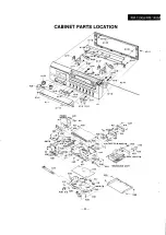
Page 28: ...RM 1300A RM 1400A CABINET PARTS LOCATION oon K33 eS ok Ks K23 DECK LOGIC PB...
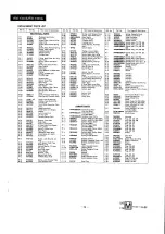
Page 29: ...M 28 RFS295Z Spring Pinch Rotter Arm M tg Ass y M 96 RBC482Y Button REW M 29 XSN2 4 Screw Playback Head M tg M 97 RBC482Z Button FF K 26 XNS7D Nut Voiume Mute Int Cum M 30 RFS293Z Plate Spring Playbac...