


6.1.2.1. Notes in chart
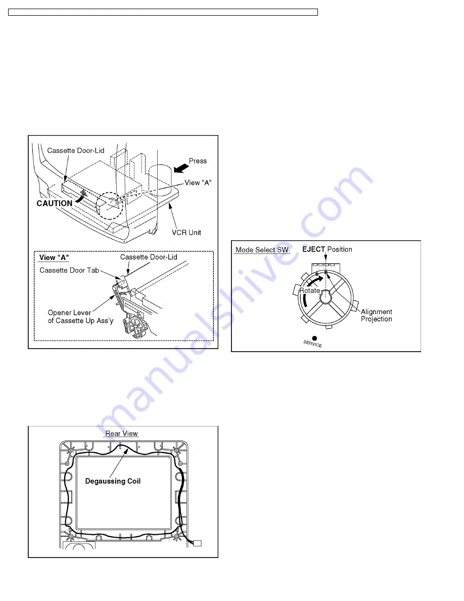
1. Installation of VCR Unit
CAUTION:
Opener Lever may be damaged when VCR Unit is
installed, with Cassette Door-Lid and Opener Lever of
Cassette Up Ass'y set incorrectly.
a. When installing the VCR Unit, swing the Cassette Door-
Lid all the way open until the Cassette Door tab clears
the Opener Lever.
b. Make sure that all guide tabs are aligned properly.
Then, press the VCR Unit straight in.
Fig. D6
2. Removal of CRT Unit
Place the Unit face down on a soft cloth before removing
the CRT Unit.
Installation of CRT Unit (Model: A, B, C, D, E, F, G)
When installing Degaussing Coil, place the Degaussing Coil
correct position.
Fig. D7
3. Installation of VCR Chassis Unit
When installing 2 Screws (S-7), slide the Holder Unit of the
Cassette
Up
Ass'y
(Refer
to
"METHOD
FOR
LOADING/UNLOADING OF MECHANISM" in SERVICE
NOTES) to tighten screws. Then, slide it back to the EJECT
Position.
Make sure that Mechanism and Cassette Up Ass'y are in
the
EJECT
Position.
(Refer
to
"EJECT
Position
Confirmation"
in
DISASSEMBLY/ASSEMBLY
PROCEDURES.)
4. Removal of TV/VCR Main C. B. A.
Work carefully so as not to break Sensor LED when lifting
the Mechanism Chassis and Cassette Up Ass'y.
Installation of Mechanism Chassis and Cassette Up
Ass'y onto TV/VCR Main C.B.A.
a. Make sure the Mode Select SW. on the TV/VCR Main
C.B.A. is in EJECT position. If not, rotate the Mode
Select SW. until the alignment projection is in the
EJECT Position.
b. Make sure the Mechanism and Cassette Up Ass'y are in
the
EJECT
Position.
(Refer
to
"EJECT
Position
Confirmation"
in
DISASSEMBLY/ASSEMBLY
PROCEDURES.)
Fig. D8
c.
Install the Mechanism Chassis and Cassette Up Ass'y
straight onto the TV/VCR Main C.B.A. so that the
Sensor LED clears the hole in the Mechanism Chassis
and that 4 Connectors (P6201, P6202, P3001, and
P4001) are aligned and seated securely.
5. Installation of Cassette Up Ass'y
a. Confirm that the Locking Tab (L-2) under the Cassette
Up Ass'y is in Hole on the Mechanism Chassis when
installing the Cassette Up Ass'y. Then, slide the
Cassette Up Ass'y towards the back.
b. When installing 2 Screws (S-9), slide the Holder Unit
(Refer to "METHOD FOR LOADING/UNLOADING OF
MECHANISM" in SERVICE NOTES) to tighten screws.
Then, slide it back to the EJECT Position.
c.
Hook Spring (P-1) to the Drive Rack Arm on the
Mechanism Chassis.
26
PVQ-1310 / PV-C1320 / PV-C1330W / VV-1300 / VV-1310W / PV-C1340 / PV-C1350W / PV-C2010 / PV-C2020 / PV-C2030W / VV-2000 / PV-C2060