Panasonic PT-VW535N Operating Instructions Manual Download Page 110

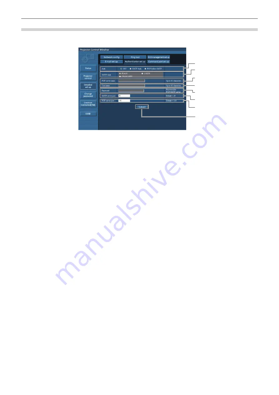
 [Authentication set up] page 

Set the authentication items when POP authentication or SMTP authentication is necessary to send an E-mail.
Click [Detailed set up] → [Authentication set up].

1
2
3
4
5
6

7

8

1  [Auth]

Select the authentication method specified by your 

Internet service provider.

2  [SMTP Auth]

Set when the SMTP authentication is selected.

3  [POP server name]

Enter the POP server name.

Allowed characters:

Alphanumerics (A - Z, a - z, 0 - 9)

Minus sign (-) and period (.)

4  [User name]

Enter the user name for the POP server or the SMTP 

server.

5  [Password]

Enter the password for the POP server or the SMTP 

server.

6  [SMTP server port]

Enter the port number of the SMTP server.

(Normally 25)

7  [POP server port]

Enter the port number of the POP server.

(Normally 110)

8  [Submit]

Update the settings.

110 -


ENGLISH

Chapter 4   Settings - [NETWORK/USB] menu

Summary of Contents for PT-VW535N

Page 1: ...ct This manual is intended for products manufactured from May 2016 and beyond Before operating this product please read the instructions carefully and save this manual for future use Before using your projector be sure to read Read this first Æ pages 2 to 11 Model No PT VZ575N PT VW535N PT VX605N ENGLISH TQBJ0730 4 ...

Page 2: ... RISK OF FIRE OR ELECTRIC SHOCK DO NOT EXPOSE THIS PRODUCT TO RAIN OR MOISTURE o AVERTISSEMENT RISQUE DE CHOC ÉLECTRIQUE NE PAS OUVRIR WARNUNG ZUR VERMEIDUNG EINES ELEKTRISCHEN SCHLAGES GERÄT NICHT ÖFFNEN ПРЕДУПРЕЖДЕНИЕ ОПАСНОСТЬ ПОРАЖЕНИЯ ЭЛЕКТРИЧЕСКИМ ТОКОМ НЕ ОТКРЫВАТЬ 경고 감전 위험이 있으므로 열지마십시오 The lightning flash with arrowhead symbol within an equilateral triangle is intended to alert the user to...

Page 3: ...perate this device FCC NOTICE USA and Canada This device complies with Part 15 of FCC Rules and RSS Gen of IC Rules Operation is subject to the following two conditions 1 This device may not cause harmful interference and 2 this device must accept any interference received including interference that may cause undesired operation of this device This transmitter must not be co located or operated i...

Page 4: ...Do not remove the Wireless LAN Module from the host product during operations Data transmitted and received over radio waves may be intercepted and monitored To avoid malfunctions caused by radio wave interface keep the host product away from the devices such as other wireless LAN devices microwaves and the devices that use 2 4 GHz and 5 GHz signals when using the Wireless LAN Module When noises o...

Page 5: ... be removed and the plug cut off and disposed of safely There is a danger of severe electrical shock if the cut off plug is inserted into any 13 amp socket If a new plug is to be fitted please observe the wiring code as shown below If in any doubt please consult a qualified electrician WARNING THIS APPLIANCE MUST BE EARTHED IMPORTANT The wires in this mains lead are coloured in accordance with the...

Page 6: ...vazamento provocar calor ruptura da blindagem e produzir fogo devido ao curto circuito dos terminais Não incinere nem aqueça as baterias elas não podem ficar expostas a temperaturas superiores a 100 C 212 F O gás liberado pela bateria pode irritar a garganta danificar o lacre do invólucro ou o vazamento provocar calor ruptura da blindagem e produzir fogo devido ao curto circuito dos terminais prov...

Page 7: ...y cloth regularly Do not handle the power plug and power connector with wet hands Failure to observe this will result in electric shocks Do not overload the wall outlet If the power supply is overloaded ex by using too many adapters overheating may occur and fire will result ON USE INSTALLATION Do not place the projector on soft materials such as carpets or sponge mats Doing so will cause the proj...

Page 8: ...he batteries to come into contact with metallic objects such as neck laces or hairpins z z Do not store or carry batteries together with metallic objects z z Store the batteries in a plastic bag and keep them away from metallic objects z z Make sure the polarities and are correct when inserting the batteries z z Do not use a new battery together with an old battery or mix different types of batter...

Page 9: ...e and burns to clothing z z Extremely strong light is emitted from the projector s lens Always disconnect all cables before moving the projector Moving the projector with cables still attached can damage the cables which will cause fire or electric shocks to occur When mounting the projector on the ceiling keep mounting screws and power cord from contact with metal parts inside the ceiling Contact...

Page 10: ...ptc panasonic de Coordonnées dans l UE Panasonic Marketing Europe GmbH Panasonic Testing Center Winsbergring 15 22525 Hamburg Germany Ce produit est conçu pour l utilisation dans les pays suivants Autriche Belgique Bulgarie République Tchéquie Chypre Danemark Estonie Finlande France Allemagne Grèce Hongrie Islande Irlande Italie Lettonie Lituanie Luxembourg Malte Pays Bas Norvège Pologne Portugal ...

Page 11: ...Important Safety Notice ENGLISH 5 Important Information Hrvatski Read this first ENGLISH 11 ...

Page 12: ...from a video provider licensed to provide AVC VC 1 MPEG 4 Video No license is granted or shall be implied for any other use Additional information may be obtained from MPEG LA LLC See http www mpegla com f f Other names company names or product names used in these operating instructions are the trademarks or registered trademarks of their respective holders Please note that the operating instructi...

Page 13: ...e cost Reference f f Lamp 5 000 Hours LAMP POWER is set to NORMAL 7 000 Hours LAMP POWER is set to ECO f f Filter 7 000 Hours This time is only the target for replacement and not the warranty time Multi device Connect Extensions With the supplied application software Wireless Manager ME6 2 and Miracast function you can project the display screen on the devices over wireless LAN Memory viewer funct...

Page 14: ... Projector 44 Direct Power Off function 44 Projecting 45 Selecting the input signal 45 How to adjust the state of the image 45 Basic operations by using the remote control 46 Using the AUTO SETUP function 46 Using the SCREEN ADJ button 46 Controlling the volume of the speaker 47 Using the FUNCTION button 47 Switching the input signal 47 Using the MEMORY VIEWER function 48 Using the Miracast functi...

Page 15: ...MX D D 94 Crestron Connected TM 95 EXTRON XTP 95 DIGITAL INTERFACE BOX 95 LIVE MODE CUT IN 95 MULTI LIVE 95 MEMORY VIEWER 96 VueMagic TM 96 STATUS 97 INITIALIZE 97 Network connections 98 Accessing from the web browser 102 Chapter 5 Operation of Function Memory Viewer function 119 What you can project with the Memory Viewer function 119 Cautions on using USB Memory 119 Displaying the Memory Viewer ...

Page 16: ...Chapter 1 Preparation This chapter describes things you need to know or check before using the projector 16 ENGLISH ...

Page 17: ... interfere with the operation of the projector r r Be sure to ask a specialized technician when installing the product to a ceiling This requires an optional ceiling mount bracket Be sure to use the Projector Mount Bracket together with the ceiling mount bracket for high ceilings or low ceilings Model No ET PKL100H for high ceilings ET PKV400B Projector Mount Bracket ET PKL100S for low ceilings ET...

Page 18: ...orized operation of this product by a malicious third party f f Interfering or stopping of this product by a malicious third party Security instruction Æ pages 85 94 113 f f Make your password as difficult to guess as possible f f Change your password periodically f f Panasonic or its affiliate company never inquires a password directly to a customer Do not tell your password in case you receive s...

Page 19: ...ten the life of the built in motor r r Lamp The light source of the projector is a high pressure mercury lamp A high pressure mercury lamp has the following characteristics f f The luminance of the lamp will decrease by duration of usage f f The lamp may burst with a loud sound or have its service life shortened because of shock chipping or degradation due to cumulative runtime f f The lamp life v...

Page 20: ...tricity such as on a carpet the wireless LAN or wired LAN connection may be lost If the static electricity or noise make it impossible to establish a connection with the LAN please press the power button on the remote control or the control panel to power off the projector and eliminate the source of static electricity or noise then turn on the projector r r Using the projector outside the country...

Page 21: ... communications and issue false data tampering Spread harmful software such as a computer virus and crash your data and or system system crash Since most wireless LAN adapters or access points are equipped with security features to take care of these problems you can reduce the possibility of these problems occurring when using this product by making the appropriate security settings for the wirel...

Page 22: ... VZ575N For PT VW535N and PT VX605N RGB signal cable 1 K1HY15YY0012 Attention f f After unpacking the projector discard the power cord cap and packaging material properly f f Do not use the supplied power cord for devices other than this projector f f For lost accessories consult your dealer f f Store small parts in an appropriate manner and keep them away from young children Note f f The type and...

Page 23: ...multiple projectors connected to the LAN Logo Transfer Software Windows This software allows you to transfer original images such as company logos to be displayed when projection starts to the projector Wireless Manager ME6 2 Windows Mac This software allows you to send com puter screen displays over wireless wired LAN Optional accessories Options Model No Ceiling Mount Bracket ET PKL100H for high...

Page 24: ...utton Used to turn off the audio and video temporarily Æ page 50 13 ID SET button Sets the ID number of the remote control to use for a system using multiple projectors Æ page 50 14 Remote control indicator Flashes if any button in the remote control is pressed 15 SCREEN ADJ button You can correct various types of distortion in a projected image Æ page 46 16 RETURN button Return to the previous me...

Page 25: ...the screen f f When the remote control signal receiver is lit with a fluorescent light or other strong light source the projector may become inoperative Set the projector as far from the luminous source as possible Projector body 4 1 2 3 5 4 12 13 6 6 6 6 7 8 9 10 11 r Front r Side r Rear Projection direction WARNING Keep your hands and other objects away from the air exhaust port f f Keep your ha...

Page 26: ...plays the status of the lamp 4 Temperature indicator TEMP Displays the status of the internal temperature 5 Ambient Luminance sensor Detects room s light and select proper image quality 6 MENU button Displays or hides the main menu Æ page 53 7 ENTER button Determines and executes an item in the menu screen 8 INPUT SELECT button Switches the input signal to project Æ page 47 9 asqw buttons Navigate...

Page 27: ...ory directly Æ page 119 7 DIGITAL LINK LAN terminal This is the LAN terminal to connect to the network This is also used when connecting a device for transmitting video and audio signals via the LAN terminal 8 SERIAL IN terminal This is the RS 232C compatible terminal to externally control the projector by connecting a computer 9 VIDEO IN terminal This is the terminal to input video signals 10 AUD...

Page 28: ...st you need to complete the Initial setting and then after setting the ID number of the projector set the ID number on the remote control About Initial setting please refer to When the initial setting screen is displayed x page 42 The factory default ID number of the unit the projector and the remote control is set to ALL you can control with this setting If necessary please set the ID number to t...

Page 29: ...for the lens cap please according to the following procedures attach the lens cap with the string of accessories 1 Thread the thinner end of the string through the hole on the lens cap Lens cap String 2 Thread the other end of the string through the hole on the bottom of the projector ENGLISH 29 Chapter 1 Preparation Attaching the Lens Cap ...

Page 30: ...Chapter 2 Getting Started This chapter describes things you need to do before using the projector such as the setup and connections 30 ENGLISH ...

Page 31: ...EILING PROJECTION METHOD FRONT DESK Parts for ceiling mount optional This requires an optional ceiling mount bracket Be sure to use the Projector Mount Bracket together with the ceiling mount bracket for high ceilings or low ceilings Model No ET PKL100H for high ceilings ET PKV400B Projector Mount Bracket ET PKL100S for low ceilings ET PKV400B Projector Mount Bracket f f Use only the ceiling mount...

Page 32: ... Minimum distance LW Maximum distance LT Height position H 0 76 30 0 78 1 27 0 025 0 228 0 70 1 15 0 002 0 186 0 68 1 12 0 022 0 201 1 02 40 1 05 1 71 0 034 0 306 0 95 1 55 0 003 0 250 0 93 1 51 0 030 0 270 1 27 50 1 32 2 14 0 042 0 381 1 19 1 94 0 004 0 311 1 16 1 89 0 037 0 337 1 52 60 1 58 2 57 0 051 0 456 1 43 2 33 0 005 0 372 1 39 2 26 0 045 0 403 1 78 70 1 86 3 01 0 059 0 534 1 69 2 73 0 005...

Page 33: ...67 1 683 7 62 300 8 63 14 01 0 091 2 286 7 83 12 72 0 124 1 867 7 62 12 37 0 081 2 019 For PT VX605N All measurements below are approximate and may differ slightly from the actual measurements Unit m Projection size 4 3 aspect ratio 16 9 aspect ratio Screen diagonal SD Minimum distance LW Maximum distance LT Height position H Minimum distance LW Maximum distance LT Height position H 0 76 30 0 69 1...

Page 34: ...2 Adjusting adjustable feet Lift the front of the projector and press the feet lock latches on both side of the projector Release the feet lock latches to lock the adjustable feet and rotate the adjustable feet to a proper height and tilt Extend the adjustable feet by rotating in the direction shown in the figure and retract by rotating in the opposite direction Feet lock latches Adjustable range ...

Page 35: ... projection position Projection screen width Projection screen height 1 V 0 40 V Attention f f If various types of distortion occur on the projected image perform SCREEN ADJUSTMENT from the POSITION menu Æ page 62 or 64 f f Please note the followings when using the projector g g Do not touch the lens while it is moving as this could cause injury to the fingers g g Never allow children to touch the...

Page 36: ...lable for connection of the device prepare a necessary system connection cable to suit the device f f Video signals containing too much jitter may cause the images on the screen to randomly wobble or wafture In this case a time base corrector TBC must be connected f f The projector accepts VIDEO signals Y C signals YCB CR YPB PR signals and analog RGB signals synchronous signals are TTL level and ...

Page 37: ...nstandard burst signals are connected the image may be distorted In such case connect the time base corrector TBC between the projector and the external devices Note f f For an HDMI cable use an HDMI High Speed cable that conforms to HDMI standards If a cable that does not conform to HDMI standards is used images may be interrupted or may not be displayed f f This projector does not support the Vi...

Page 38: ...tor f f If the AUDIO IN SELECT settings are incorrect the projector may have malfunctions such as the absence of audio x page 83 f f When the VARIABLE AUDIO OUT terminal is connected with cable the sound will not be output from the built in speaker Connecting example Twisted pair cable transmitter Twisted pair cable transmitters such as the optional Digital Interface Box Model No ET YFB100G use tw...

Page 39: ... the projector This may cause image and sound to be disrupted f f Do not pull cables forcefully Also do not bend or fold cables unnecessarily f f To reduce the effects of noise as much as possible stretch out the cables between the twisted pair cable transmitter and the projector without any loops f f Lay the cables between a twisted pair cable transmitter and the projector away from other cables ...

Page 40: ...Chapter 3 Basic Operations This chapter describes basic operations to start with 40 ENGLISH ...

Page 41: ...ressing the side tabs Power indicator Displays the status of the power Check the ON G STANDBY R status of the power indicator before operating the projector Power indicator ON G STANDBY R Indicator status Status Off The power cord is unplugged Red Lighting The power is switched off in standby mode The ECO MANAGEMENT x STANDBY MODE is set to ECO Blinking 1 The power is switched off in standby mode ...

Page 42: ...jected on the screen Attention f f Be sure to remove the lens cap before starting projection Note f f If the PROJECTOR SETUP menu ECO MANAGEMENT STANDBY MODE is set to ECO Æ page 81 it may take approx 10 seconds longer before the projector starts projecting after the power is turned on compared with when NORMAL is set f f If the PROJECTOR SETUP menu ECO MANAGEMENT STANDBY MODE is set to NORMAL it ...

Page 43: ...you can change the setting from the PROJECTOR SETUP menu ECO MANAGEMENT STANDBY MODE 81 2 Press qw to switch the setting 3 Press the ENTER button f f Confirm the setting value and complete the initial setting Note f f If you press the RETURN button in the initial setting projector setup screen you can go back to the initial setting display language screen Making adjustments and selections It is re...

Page 44: ...til the power indicator ON G STANDBY R lights or blinks in red f f The projector enters standby mode when the power indicator ON G STANDBY R lights or blinks in red Note f f While the power indicator ON G STANDBY R is lighting in orange the lamp is being cooled down and the projector cannot be turned on Wait until the power indicator ON G STANDBY R starts lighting or blinking in red to turn on the...

Page 45: ...ing of the projector and the screen is correctly installed adjust the focus and zoom 1 Adjust the projection angle f f Install the projector on a flat surface and parallel to the screen so that the projected screen is rectangular f f If the screen is tilted downward extend the adjustable feet and adjust the projection screen so that the projected screen is rectangular f f For details see Adjusting...

Page 46: ... few seconds during automatic adjustment but it is not a malfunction f f If you press any button on the remote control during the automatic adjustment the automatic adjustment will be canceled f f If the automatic setup function is used while moving images are being input the adjustment may not be performed properly even for an RGB signal that can use automatic setup Using the SCREEN ADJ button Yo...

Page 47: ...n for 3 seconds or more Note f f After settings have been completed the assigned menu item main menu sub menu or details menu will be displayed in ASSIGNED FUNCTION of the operation guide under the menu f f Perform the PROJECTOR SETUP menu FUNCTION BUTTON Æ page 82 when deallocating functions Switching the input signal You can switch the input signals to project buttons 1 Press COMPUTER 1 COMPUTER...

Page 48: ...will be displayed Æ page 93 Using the Miracast function This function is to project the displayed images on the Miracast certified device to the projector through the wireless LAN connection button 1 Press the Miracast button on the remote control f f Switches the input to Miracast Note f f For details see About Miracast Æ page 125 f f When MEMORY VIEWER or Panasonic APPLICATION is selected in CON...

Page 49: ...menu Operation Adjustment Press the as buttons Moves the area to the top or the bottom Press the qw buttons Moves the area to the left or the right f f When you have executed the operation of remote control directly the individual adjustment screen is not displayed and the operation menu of the moving screen is displayed At this time you can adjust the magnification by using the D ZOOM button or D...

Page 50: ... remote control f f The count is started f f The elapsed time or the remaining time is displayed at the bottom right of the projected image 2 Press the P TIMER button again f f The count is stopped 3 Press the P TIMER button again f f The count is resumed Note f f Pressing the P TIMER button for at least 3 seconds to release the P TIMER function f f For details please refer to the DISPLAY OPTION m...

Page 51: ...projector Attention f f Since the ID number of the remote control can be set without the projector do not press the ID SET button on the remote control carelessly If the ID SET button is pressed and no number 1 6 buttons are pressed within five seconds the ID number returns to its original value before the ID SET button was pressed f f The ID number set on the remote control will be stored unless ...

Page 52: ...Chapter 4 Settings This chapter describes the settings and adjustments you can make using the on screen menu 52 ENGLISH ...

Page 53: ... item from the main menu f f The selected item is highlighted in yellow 3 Press the ENTER button f f The submenu is displayed and submenu items become selectable 4 Press as to select the desired sub menu item press qw or the ENTER button to set or adjust settings f f Some items will switch in order as follows each time you press qw A B C f f For some items press qw to display an individual adjustm...

Page 54: ...ssed the values adjusted in the menu items are restored to the factory default settings button 1 Press the DEFAULT button on the remote control Note f f You cannot reset all the settings to the factory default at a time f f To reset all the settings adjusted in the sub menu item to the factory default at a time execute the PROJECTOR SETUP menu INITIALIZE ALL Æ page 84 f f Some items cannot be rese...

Page 55: ...ngs may vary depending on the picture mode POSITION Sub menu item Factory default Page REALTIME KEYSTONE ON 62 SCREEN ADJUSTMENT 62 64 SHIFT 67 DOT CLOCK 1 0 68 CLOCK PHASE 1 0 68 OVER SCAN 68 ASPECT 69 FRAME LOCK 1 OFF 69 1 Only for still image signals LANGUAGE Details Æ page 70 DISPLAY OPTION Sub menu item Factory default Page ON SCREEN DISPLAY 71 HDMI SIGNAL LEVEL AUTO 72 DIGITAL LINK SIGNAL LE...

Page 56: ...IGITAL LINK MODE AUTO 88 DIGITAL LINK SETUP 88 DIGITAL LINK STATUS 89 WIRED LAN 89 WIRELESS LAN SIMPLE 90 CONNECTION LOCK OFF 93 NAME CHANGE 94 PASSWORD OFF 94 PASSWORD CHANGE 94 NETWORK CONTROL ON 94 AMX D D OFF 94 Crestron Connected TM OFF 95 EXTRON XTP OFF 95 DIGITAL INTERFACE BOX 95 LIVE MODE CUT IN OFF 95 MULTI LIVE 1 95 MEMORY VIEWER 96 VueMagic TM OFF 96 STATUS 97 INITIALIZE 97 1 Only for P...

Page 57: ...he picture becomes suitable for projecting on a white board CINEMA 1 The picture becomes suitable for movie sources NATURAL 2 The picture becomes suitable for use in low light areas 1 Only for the movie based signals 2 Only for the still image signals CONTRAST You can adjust the contrast of the colors 1 Press as to select CONTRAST 2 Press qw or the ENTER button f f The CONTRAST individual adjustme...

Page 58: ...een is displayed 3 Press qw to adjust the level Operation Adjustment Adjustment range Press the w button Adjusts skin tone toward greenish color 32 32 Press the q button Adjusts skin tone toward reddish purple SHARPNESS You can adjust the sharpness of the projected image 1 Press as to select SHARPNESS 2 Press qw or the ENTER button f f The SHARPNESS individual adjustment screen is displayed 3 Pres...

Page 59: ...ess the q button Deemphasizes red in highlight areas CONTRAST G Press the w button Emphasizes green in highlight areas 32 32 Press the q button Deemphasizes green in highlight areas CONTRAST B Press the w button Emphasizes blue in highlight areas 32 32 Press the q button Deemphasizes blue in highlight areas BRIGHTNESS R Press the w button Emphasizes red in shadow areas 32 32 Press the q button Dee...

Page 60: ... qw to switch the item f f The items will switch each time you press the button OFF Disables NOISE REDUCTION ON Enables NOISE REDUCTION 1 When COMPUTER1 INPUT SETTING is set to Y C Æ page 78 Attention f f When this is set for an input signal with less noise the image may look different from what it originally was In such a case set it to OFF TV SYSTEM Only when the VIDEO IN terminal or COMPUTER 1 ...

Page 61: ...nal is selected f f For 525i 480i 625i 576i 525p 480p and 625p 576p input Select AUTO RGB or YCB CR f f For other movie based signal input Select AUTO RGB or YPB PR 1 When the COMPUTER 2 IN 1 OUT terminal is used as COMPUTER 2 IN terminal When the HDMI 1 IN HDMI 2 IN DIGITAL LINK terminal is selected f f For 525p 480p and 625p 576p input Select AUTO RGB or YCB CR f f For other movie based signal i...

Page 62: ...uired f f The REALTIME KEYSTONE function cannot work when the FRONT CEILING or REAR CEILING feature is selected in PROJECTION METHOD in the PROJECTOR SETUP menu SCREEN ADJUSTMENT For PT VW535N and PT VX605N You can correct the trapezoidal distortion and the curved distortion of the projected image 1 Press as to select SCREEN ADJUSTMENT 2 Press the ENTER button f f The SCREEN ADJUSTMENT screen is d...

Page 63: ...ER CORRECTION individual adjustment screen is displayed 6 Press asqw to adjust CORNER CORRECTION UPPER LEFT UPPER RIGHT LOWER LEFT LOWER RIGHT Setting CURVED CORRECTION 1 Press as to select SCREEN ADJUSTMENT 2 Press the ENTER button f f The SCREEN ADJUSTMENT screen is displayed 3 Press as to select CURVED CORRECTION 4 Press the ENTER button f f The CURVED CORRECTION screen is displayed 5 Press as ...

Page 64: ...e tilt in the vertical direction and 35 for the tilt in the horizontal are available for adjustments with KEYSTONE However the image quality will degrade and it will get harder to focus with more correction Install the projector so that the correction will be as small as possible f f Screen size will also change when KEYSTONE is used to perform various adjustments f f Aspect ratio of the image siz...

Page 65: ...ust the item f f The adjustment values are 0 9 to 2 3 Adjusting KEYSTONE 1 Press as to select SCREEN ADJUSTMENT 2 Press the ENTER button f f The SCREEN ADJUSTMENT screen is displayed 3 Press as to select KEYSTONE 4 Press the ENTER button f f The KEYSTONE screen is displayed 5 Press as to select KEYSTONE 6 Press the ENTER button f f The KEYSTONE individual adjustment screen is displayed 7 Press asq...

Page 66: ... Press the ENTER button f f The CORNER CORRECTION screen is displayed 5 Press as to select the item to adjust then press the ENTER button f f The CORNER CORRECTION individual adjustment screen is displayed 6 Press asqw to adjust CORNER CORRECTION UPPER LEFT UPPER RIGHT LOWER LEFT LOWER RIGHT LINEARITY Horizontal direction LINEARITY Horizontal direction Vertical direction LINEARITY Vertical directi...

Page 67: ...STONE CORNER CORRECTION or CURVED CORRECTION screen is displaying it will switch to the next adjustment screen f f When the CORNER CORRECTION individual adjustment screen is displaying the individual adjustment screen of the next corner can also be displayed by pressing the ENTER button f f Correcting up to 25 for the tilt in the vertical direction and 30 for the tilt in the horizontal are availab...

Page 68: ...ignals and YCB CR YPB PR signals input You can adjust to achieve an optimal image when there is a flickering image or smeared outlines 1 Press as to select CLOCK PHASE 2 Press qw or the ENTER button f f The CLOCK PHASE individual adjustment screen is displayed 3 Press qw to adjust the value f f Adjustment value will change between 16 and 16 Adjust so that the amount of interference is at a minimum...

Page 69: ...2 Standard signals are input signals with an aspect ratio of 4 3 or 5 4 3 Wide screen signals are input signals with an aspect ratio of 16 10 16 9 or 15 9 Note f f The image size may be switched abnormally when AUTO is selected please set to NORMAL or WIDE according to the input signal f f Some size modes are not available for certain types of input signals f f If an aspect ratio which is differen...

Page 70: ...us menus settings adjustment screens control button names etc are displayed in the selected language f f The language can be changed to English German French Italian Spanish Portuguese Dutch Swedish Finnish Norwegian Danish Polish Hungarian Romanian Czech Russian Turkish Arabic Kazakh Vietnamese Chinese Korean Japanese and Thai Note f f The on screen display language of the projector is set to Eng...

Page 71: ...e you press the button DETAILED Displays the name of input terminal and input signal graphically OFF Disables the input guide SIMPLE Displays the name of input terminal and input signal OSD POSITION Set the position of the menu screen OSD 1 Press as to select ON SCREEN DISPLAY 2 Press the ENTER button f f The ON SCREEN DISPLAY screen is displayed 3 Press as to select OSD POSITION 4 Press qw to swi...

Page 72: ...mputer or other device is connected to the HDMI 1 IN HDMI 2 IN terminal Note f f The optimal setting varies depending on the output setting of the connected external device Refer to the operation instruction of the external device regarding the output of the external device f f The displayed signal level is assumed when the input is 30 bits DIGITAL LINK SIGNAL LEVEL Switch the setting when the ext...

Page 73: ...n that displays text information of video signals mainly used in North America Captions may not be displayed depending on the connected devices or contents being played back f f CLOSED CAPTION SETTING can only be selected if an NTSC or 480i YCB CR signal is input f f If CLOSED CAPTION SETTING is set to ON the brightness of image may be changed according to the external devices or the used content ...

Page 74: ...will displayed at the top LOW The image which aspect ratio is 16 9 will displayed at the bottom r When SCREEN FORMAT is 4 3 Only for PT VZ575N CENTER The image which aspect ratio is 4 3 will displayed at the center LEFT The image which aspect ratio is 4 3 will displayed in the left RIGHT The image which aspect ratio is 4 3 will displayed at the right STARTUP LOGO Set the logo display when the powe...

Page 75: ...blue BLACK Displays the entire projection area in black DEFAULT LOGO Displays the Panasonic logo USER LOGO Displays the image registered by the user Note f f To create register the USER LOGO image use Logo Transfer Software included in the supplied CD ROM f f If you do not register the image of the USER LOGO the projected image will be displayed in black even if the BACK COLOR is set to USER LOGO ...

Page 76: ...OP The count is stopped RESTART The count is resumed RESET The count is reset f f When START or RESTART is selected the elapsed time or the remaining time is displayed at the bottom right of the projected image f f When STOP is selected the elapsed time or the remaining time when the count was stopped is displayed at the bottom right of the projected image f f When RESET is selected proceed to Ste...

Page 77: ...UP For details refer to Using the AUTO SETUP function Æ page 46 FREEZE The projected image is paused temporarily and the sound stopped regardless of the playback of the external equipment To release this function press the RETURN button or the FREEZE button on the remote control AV MUTE Turn off audio and image when the projector is not used for a certain period of time To release this function pr...

Page 78: ...equired to calculate the rough estimate for lamp replacement Formula for lamp replacement time rough estimate A 1 B 5 7 f f A Runtime which is displayed in STATUS screen RUNTIME LAMP NORMAL f f B Runtime which is displayed in STATUS screen RUNTIME LAMP ECO 2 The model No of the optional lamp unit is subject to change without prior notice COMPUTER1 INPUT SETTING Set whether to use the COMPUTER 1 IN...

Page 79: ...rol INITIAL START UP Set the method of start up when the power cord plugged into the AC outlet 1 Press as to select INITIAL START UP 2 Press qw to switch the item f f The items will switch each time you press the button LAST MEMORY Starts in the condition that before disconnected the power cord or turn off the breaker STANDBY Starts up in the standby mode ON Starts the projection immediately PROJE...

Page 80: ...ed automatically in the following cases When the lamp lighting is just completed or the setting of LAMP POWER is just completed etc f f When AUTO POWER SAVE is set to OFF settings of AMBIENT LIGHT DETECTION SIGNAL DETECTION AV MUTE DETECTION are unavailable f f When objects etc are placed around the luminance sensor on the top of the projector AMBIENT LIGHT DETECTION may not function properly Sett...

Page 81: ...control commands on a previously purchased Panasonic projector This allows the control software for an existing Panasonic projector to be inherited and used 1 Press as to select EMULATE 2 Press the ENTER button f f The EMULATE screen is displayed 3 Press as to select the desired item DEFAULT VZ575N series VW535N series VX605N series VZ570 series VW530 series VX600 series VX60 EZ580 series EW640 se...

Page 82: ...ETTING screen is displayed 3 Press as to select VOLUME 4 Press qw to adjust the level Operation Adjustment Range Press the w button Increases the volume 0 63 Press the q button Decreases the volume Setting the mute 1 Press as to select AUDIO SETTING 2 Press the ENTER button f f The AUDIO SETTING screen is displayed 3 Press as to select MUTE 4 Press qw to switch the item OFF Audio is output ON Audi...

Page 83: ...IO IN 3 HDMI2 Select one item among HDMI2 AUDIO IN AUDIO IN 1 AUDIO IN 2 or AUDIO IN 3 DIGITAL LINK Select one item among DIGITAL LINK AUDIO IN AUDIO IN 1 AUDIO IN 2 or AUDIO IN 3 NETWORK USB Select one item among NETWORK USB AUDIO IN AUDIO IN 1 AUDIO IN 2 or AUDIO IN 3 Note f f When MIC is set to ON AUDIO IN 2 cannot be selected f f Even if AUDIO IN 2 is selected it will change to AUDIO IN 1 auto...

Page 84: ...filter replacement FILTER COUNTER RESET Resets the filter counter Setting TIMER 1 Press as to select TIMER 2 Press qw to switch the setting of the timer f f The items will switch each time you press the button OFF 1000 H 2000 H 3000 H 4000 H 5000 H 6000 H 7000 H FILTER COUNTER RESET 1 Press as to select FILTER COUNTER RESET 2 Press the ENTER button f f The FILTER COUNTER RESET screen is displayed ...

Page 85: ...he control panel or on the remote control 1 Press as to select PASSWORD 2 Press qw to switch the item f f The items will switch each time you press the button OFF Disables the security password entry ON Enables the security password entry Note f f The PASSWORD setting is set to OFF by the factory default f f Change the password periodically that is hard to guess f f The security password is enable...

Page 86: ...ach time you press the button OFF Unlocks menu operations ON Locks menu operations Note f f When the entered password is incorrect after setting MENU LOCK to ON the MENU button cannot be operated f f MENU LOCK is set to OFF at the time of purchase or when INITIALIZE ALL is executed f f When MENU LOCK is set to ON and then enter the password to release the lock the unlock state is held until the pr...

Page 87: ...ble the button operations DISABLE Disable the button operations f f A confirmation screen will be displayed when you change ENABLE to DISABLE then proceed to Step 5 5 Press qw to select OK and then press the ENTER button Note f f When a button operation is performed on the device set to DISABLE the PASSWORD screen is displayed To continue operations enter the security password f f The PASSWORD scr...

Page 88: ...AL LINK MODE 2 Press qw to switch the item f f The items will switch each time you press the button AUTO Switches the communication method automatically to DIGITAL LINK or Ethernet DIGITAL LINK Fixes the communication method to DIGITAL LINK ETHERNET Fixes the communication method to Ethernet Possible communication modes Setting Communication possible Image transmission Ethernet RS 232C AUTO For DI...

Page 89: ...mation screen is displayed press qw to select OK and press the ENTER button DIGITAL LINK STATUS Display DIGITAL LINK connection environment 1 Press as to select DIGITAL LINK STATUS 2 Press the ENTER button f f The DIGITAL LINK STATUS screen is displayed LINK STATUS Either NO LINK DIGITAL LINK or ETHERNET is displayed HDCP STATUS Either NO SIGNAL OFF or ON is displayed SIGNAL QUALITY SIGNAL QUALITY...

Page 90: ...s LAN function SIMPLE Simple connection mode that can be compatible with all OS Windows Mac iOS Android etc Use the wireless LAN function via the application software which supports Wireless Manager ME6 2 iPad iPhone iPod touch and Android devices NORMAL S DIRECT Use this setting when use the wireless LAN function via the software Wireless Manager ME6 2 of the supplied CD ROM which supports Window...

Page 91: ...ct the projector to computer via the infrastructure In addition the connection with iPad iPhone iPod touch Android is much easier 1 Press the ENTER button when NORMAL is selected f f The NORMAL screen is displayed 2 Press qw to select M DIRECT and press the ENTER button f f The WIRELESS DETAILED SETUP screen is displayed 3 Press as to select an item and press qw to change the setting according to ...

Page 92: ...e segment 4 Press s f f The WIRELESS DETAILED SETUP 2 2 screen is displayed 5 Press as to select the item and press asqw to change the setting according to the instructions SSID Enter the same character string that is registered in the access point AUTHENTICATION Set the user authentication method used by the network to be connected OPEN Select when the access point authentication method is Open S...

Page 93: ...according to the setting of the RADIUS server Check with the network administrator for the setting of the RADIUS server f f When using an EAP together with an access point with invalid SSID broadcast select WPA EAP or WPA2 EAP for the authentication method even if the authentication method of the access point is WPA EAP or WPA2 EAP f f If USER1 3 is used you cannot connect to the access point of s...

Page 94: ...check when connecting with the projector using Wireless Manager ME6 2 Default OFF f f When using the deliver image to all function or the delivered image deletion function of the Multi Projector Monitoring Control Software image cannot be delivered to the projector with password setting set to ON To use these image delivery functions set it to OFF PASSWORD CHANGE 1 Press as to select PASSWORD CHAN...

Page 95: ...INK LAN terminal the main menu of ET YFB100G is displayed Refer to the Operating Instructions of ET YFB100G for details Note f f When EXTRON XTP is set to ON DIGITAL INTERFACE BOX cannot be selected LIVE MODE CUT IN Set this ON to allow interrupt of the Live mode by other users or to allow delivery of images by the Multi Projector Monitoring Control Software while the Live mode is active sending i...

Page 96: ...ys gradually from the center to the whole FADE Displays the whole gradually BLIND Displays gradually to open a vertical blind CHECKER WIPE Displays gradually to the right from the left side in a grid pattern SLIDE IN Displays the next screen to appear from right to left SLIDE OUT Disappears the previous screen from right to left then displays the next screen GUIDE It is set to ON when the guide is...

Page 97: ...of the DHCP server IP ADDRESS Displays the IP address SUBNET MASK Displays the subnet mask DEFAULT GATEWAY Displays the default gateway DNS1 Displays the address of the primary DNS server DNS2 Displays the address of the secondary DNS server MAC ADDRESS Displays the MAC address of wired LAN WIRELESS LAN Displays the network information of the wireless LAN that set on the projector ANTENNA LEVEL Di...

Page 98: ... http www crestron com For the download of RoomView Express please refer to the website of Crestron Electronics Inc Only in English http www crestron com getroomview Computer that can be used In order to use the Web control function a Web browser is required Confirm that the Web browser can be used beforehand OS Compatible web browser Windows Internet Explorer 7 0 8 0 9 0 10 0 11 0 Mac OS Safari 4...

Page 99: ...t the cables between the twisted pair cable transmitter and the projector without any loops f f Lay the cables between a twisted pair cable transmitter and the projector away from other cables particularly power cables f f When installing multiple cables run them side by side along the shortest distance possible without bundling them together f f After laying the cables confirm that the value of S...

Page 100: ...ample of connection for image transfer Miracast Image transfer application software Connection image Projector Miracast Miracast certified device Example Copyright protection content display Projector Example Multi screen display iPad iPhone iPod touch Android mobile terminal and computer which are installed with the image transfer application software Input Miracast Panasonic APPLICATION Communic...

Page 101: ...NORMAL USER1 USER3 SSID Panasonic Projector DHCP OFF IP ADDRESS 192 168 11 100 SUBNET MASK 255 255 255 0 DEFAULT GATEWAY 192 168 11 1 AUTHENTICATION OPEN ENCRYPTION NONE DNS1 DNS2 NONE Computer settings 1 Turn on the computer 2 Make the network setting according to your system administrator f f If you select M DIRECT in WIRELESS LAN the IP address will automatically be acquired f f If you select U...

Page 102: ...or control the projector from multiple computers f f Change the password first Æ page 113 f f The administrator rights allow use of all functions The user rights allow use of Projector status Æ page 103 confirmation of the error information page Æ page 104 Network status Æ page 104 Basic control Æ page 105 Advanced control Æ page 105 and Change password Æ page 113 only f f Access will be locked fo...

Page 103: ...ojector 2 PROJECTOR NAME Displays the name set in the projector 3 MAIN VERSION Displays the firmware version of the projector 4 POWER Displays the status of the power 5 PICTURE MODE Displays the status of the picture mode 6 SERIAL NUMBER Displays the serial number of the projector 7 NETWORK VERSION Displays the version of firmware of the network 8 AV MUTE Displays the AV mute status 9 VOLUME Displ...

Page 104: ... fan 4 FAN EXHAUST Trouble has occurred in the exhaust fan FAN LAMP Trouble has occurred in the lamp cooling fan INTAKE AIR TEMPERATURE The air intake temperature is too high The projector may be used in an operating environment where the temperature is high such as near a heating appliance EXHAUST AIR TEMPERATURE The exhaust air temperature is high The air exhaust port may be blocked LAMP REMAIN ...

Page 105: ...witches between AV mute on off 5 POWER Turns on off the power 6 CLOSED CAPTION Switches the closed caption mode Note f f When NETWORK USB WIRELESS LAN is set to SIMPLE S DIRECT or M DIRECT and the web control function is enabled in the wireless LAN connection if you switch the input to MEMORY VIEWER or Miracast the wireless connection will be cut off and the web control function cannot be used any...

Page 106: ...the IP address when not using a DHCP server 3 SUBNET MASK Enter the subnet mask when not using a DHCP server 4 DEFAULT GATEWAY Enter the default gateway address when not using a DHCP server 5 DNS1 Enter the DNS1 server address Permissible characters for the entry of DNS1 server address primary Numbers 0 9 period Example 192 168 0 253 6 DNS2 Enter the DNS2 server address Permissible characters for ...

Page 107: ...e displayed by pressing the Next button Click the Submit button to update the settings Wireless LAN M DIRECT 1 2 3 4 5 6 1 IP ADDRESS Enter the IP address when not using a DHCP server 2 SUBNET MASK Enter the subnet mask when not using a DHCP server 3 SSID Set the SSID to be used in M DIRECT 4 CHANNEL Set the channel to be used in M DIRECT 5 KEY Set the key to be used in M DIRECT Input either 8 to ...

Page 108: ...Next button Click the Submit button to update the settings 8 AUTHENTICATION Set the user authentication method used by the network to be connected 9 EAP Select the EAP setup in the RADIUS server 10 ENCRYPTION Select the encryption method to be used for communication between the projector and the network Note f f The screen items will change according to the authentication method of wireless LAN wh...

Page 109: ... mail will not be sent for 60 minutes after sending the temperature warning E mail even if it reaches the warning temperature 6 INTAKE AIR TEMPERATURE Change the temperature setting for the temperature warning mail A temperature warning E mail is sent when the temperature exceeds this value 8 7 9 8 7 7 E MAIL ADDRESS 1 E MAIL ADDRESS 2 Enter the E mail address to be sent Leave E MAIL ADDRESS 2 bla...

Page 110: ...he SMTP authentication is selected 3 POP server name Enter the POP server name Allowed characters Alphanumerics A Z a z 0 9 Minus sign and period 4 User name Enter the user name for the POP server or the SMTP server 5 Password Enter the password for the POP server or the SMTP server 6 SMTP server port Enter the port number of the SMTP server Normally 25 7 POP server port Enter the port number of t...

Page 111: ...E OK EXHAUST AIR TEMPERATURE OK LAMP REMAIN TIME OK LAMP STATUS OK APERTURE CONTRAST SHUTTER OK AIR FILTER OK Error code 00 00 00 00 00 00 00 00 Intake air temperature 31 degC 87 degF Exhaust air temperature 37 degC 98 degF PROJECTOR RUNTIME 800 H LAMP ECO 500 H LAMP NORMAL 100 H LAMP REMAIN 3400 H Current status MAIN VERSION 1 00 NETWORK VERSION 1 00 SUB VERSION 1 00 LAMP STATUS LAMP ON INPUT RGB...

Page 112: ...N 3400 H Current status MAIN VERSION 1 00 NETWORK VERSION 1 00 SUB VERSION 1 00 LAMP STATUS LAMP OFF INPUT RGB Wired Network configuration DHCP Client OFF IP address 192 168 10 100 MAC address 04 20 9A 00 00 00 Wireless Network configuration DHCP Client OFF IP address 192 168 0 100 MAC address 04 20 9A 00 00 00 Memo Command port set up page Set the port number used for command control Click Detail...

Page 113: ...unction 6 POWER MANAGEMENT Select the power consumption mode 7 TIMER Select the time that the lamp is turned off when the POWER MANAGEMENT function is using 8 Submit Update the setting Note f f For detailed description of each setting item refer to the PROJECTOR SETUP menu of the projector ECO MANAGEMENT Æ page 80 Change password page Click Change password 1 2 3 1 Administrator Used to change the ...

Page 114: ...rd Up to 16 characters in single byte Password Retype Enter the desired new password again 4 OK Determines the change of password User account 1 2 3 1 Account Displays the account to change 2 New User name Enter the desired new user name Up to 16 characters in single byte Password Enter the desired new password Up to 16 characters in single byte Password Retype Enter the desired new password again...

Page 115: ...not displayed on the web control screen The control page of Crestron Connected is displayed by clicking Crestron Connected TM It is not displayed if Adobe Flash Player is not installed on the computer used or the browser used does not support Flash In that case click Back on the control page to go back to the previous page Control page 1 2 3 4 5 6 7 1 Tools Info Help Tabs for selecting the setting...

Page 116: ...ys the current setting SubnetMask Displays the current setting DefaultGateway Displays the current setting DNSServer Displays the current setting 5 Exit Returns to the control page Info page Click Info on the control page 4 5 6 7 1 2 3 8 1 Projector Name Displays the projector name 2 Mac Address Displays the MAC address 3 Lamp Hours Displays the runtime of the lamp converted value 4 Power Status D...

Page 117: ... page Click Help on the control page The Help Desk window is displayed 1 1 Help Desk Send receive messages to from an administrator who uses Crestron Connected ENGLISH 117 Chapter 4 Settings NETWORK USB menu ...

Page 118: ...Chapter 5 Operation of Function This chapter describes the operation methods of some functions 118 ENGLISH ...

Page 119: ...metal objects to the USB terminal Static electricity may cause data loss or data corruption f f Do not remove the USB memory from the computer or the projector while the USB memory is reading out or writing the data It may cause data loss or data corruption f f Do not store the USB memory where high temperature humid or dusty place or magnetized items are around Note f f It is compatible with the ...

Page 120: ...t in NETWORK USB menu MEMORY VIEWER VIEW x page 96 Operations of the Memory Viewer screen The following describes the operations after the Memory Viewer screen displays When displaying in thumbnail 1 Press the AUTO SETUP CANCEL button f f The cursor moves from the thumbnail display area on the right of the screen to the folder list on the upper left of the screen The background is orange 2 Press a...

Page 121: ...The selected folder cursor position is displayed on an orange background 3 Press as to select the desired file f f The thumbnail of the selected still image or movie file will be displayed in the information area on the lower left of the screen 4 Press the ENTER button f f The file starts playing on the full screen f f For the detailed information on the playing order refer to the Playing the stil...

Page 122: ...ns to the MEMORY VIEWER screen thumbnails When the automatic playback function is disable Introduce the procedure of the operation under the MEMORY VIEWER menu AUTOPLAY is set to OFF x page 96 In this case it will play a file one by one 1 Press asqw to select a file from the thumbnail and then press the ENTER button f f The selected still image will be played in full screen f f Press w to play the...

Page 123: ...ay from the beginning Play from the beginning f f Press w during pausing it will skip the current playing and automatic play from the next file f f Press q during pausing it will automatic play from the previous file 2 Press the AUTO SETUP CANCEL button f f Exit the automatic playback and returns to the MEMORY VIEWER screen thumbnails When the automatic playback function is disable Introduce the p...

Page 124: ...t the same video f f When you want to play the original video after playing another video file or image file Note f f During playing you can press the ENTER button to pause the video and press the AUTO SETUP CANCEL button to exit the full screen display The resume information the position where you stop the video during playing will be kept automatically f f The maximum number of the file whose re...

Page 125: ...t application name and starting method differs from devices f f For the operation of the Miracast application refer to the operation instructions of the device Disconnecting with the Miracast certified device Close the Miracast application of the device And then the Miracast idle screen will be projected If you disconnect the device forcibly without closing the application such as turning off the ...

Page 126: ...Chapter 6 Maintenance This chapter describes methods of inspection when there are problems maintenance and replacement of the units 126 ENGLISH ...

Page 127: ... taking the preceding measures ask your dealer for repair Temperature indicator TEMP Indicator status Lighting in red Blinking in red Blinking in red Slow Status The air filter unit is clogged internal temperature is high warning The air filter unit is clogged internal temperature is high standby status The projector detects an abnormal condition and cannot be turned on Check f f Is the air intake...

Page 128: ...ctor is used in dusty environment Replace the air filter unit in the following cases f f If the air filter unit is clogged a Temperature Warning message is displayed on the screen and then the temperature indicator TEMP lights red the power of the projector may be turned off automatically and entered into standby mode f f FILTER COUNTER has reached the set time is displayed When purchasing the opt...

Page 129: ...ct OK then press the ENTER button f f The filter usage time is 0 after reset Attention f f When using the projector be sure to attach the air filter unit If it is not attached the projector will suck in dirt and dust causing a malfunction f f Do not put anything into the air vents Doing so may result in malfunction of the projector f f The air filter unit to be replaced should be an unused product...

Page 130: ...ditions and the installation environment It is recommended that the Replacement lamp unit be prepared earlier In order to predict the lamp replacement time please refer to the lamp runtime displayed in STATUS x page 78 RUNTIME LAMP NORMAL ECO It also can be obtained by using the following formula The time which is displayed in ECO is the converted usage time when set to NORMAL Formula for lamp rep...

Page 131: ...3 securely with a Phillips screwdriver f f When you experience difficulty in installing the lamp unit remove it and try again If you use force to install the lamp unit the connector may be damaged 6 Attach the lamp cover Tighten the lamp cover fixing screw 1 securely with a Phillips screwdriver f f Perform Step 2 in the reverse order to attach the lamp cover Note f f When you replace the lamp unit...

Page 132: ... remote control does not operate f f The batteries may be weak f f The batteries may not have been inserted correctly 28 f f The remote control signal receiver on the projector may be obstructed 25 f f The remote control unit may be out of the operation range 25 f f Strong light such as fluorescent shine onto the signal receiver 25 f f The REMOTE CONTROLLER setting is set to DISABLE in CONTROL DEV...

Page 133: ...Attention f f If the problem persists after confirming the contents of the table please consult your dealer ENGLISH 133 Chapter 6 Maintenance Troubleshooting ...

Page 134: ... the Miracast idle screen is not displayed the sound cannot be output the connection is failed please re boot the projector and then return the operation according to the following method Set STANDBY MODE to ECO turn off the power and then turn on the power If STANDBY MODE is already set to ECO the procedure of the setting is not required Please turn off the power and disconnect the power plug fro...

Page 135: ...Chapter 7 Appendix This chapter describes specifications and after sales service for the projector ENGLISH 135 ...

Page 136: ...f f 2 Error 2nd byte Indicates lamp errors range 0 2 3rd byte Indicates temperature errors range 0 2 4th byte Fixed at 0 5th byte Indicates filter errors range 0 2 6th byte Indicates other errors range 0 2 LAMP Lamp status query 1st digits 1 5 digits Lamp cumulative operating time 2nd digit 0 Lamp off 1 Lamp on INST Input selection list query 11 12 21 31 32 33 41 51 52 NAME Projector name query Re...

Page 137: ...lgorithm f f xxxxxx yyyyy zzzzzzzz xxxxxx Administrator rights user name for WEB CONTROL Default user name is admin1 yyyyy Password of above administrator rights user Default password is panasonic zzzzzzzz 8 byte random number obtained in Step 2 Command transmission method Transmit using the following command format r r Transmitted data Header Data section Termination symbol Command example Hash v...

Page 138: ... 0x0d Data length 9 bytes 1 byte 1 byte 1 byte f fMode 0 Non protect mode Command transmission method Transmit by the following command format r r Transmitted data Header Data section Termination symbol Command example 0 0x30 0 0x30 Control command ASCII string CR 0x0d Data length 1 byte 1 byte Undefined length 1 byte r r Receive data Header Data section Termination symbol Command example 0 0x30 0...

Page 139: ... 232C x page 81 must be set according to the connection method f f When connecting by a DIGITAL LINK compatible device set the PROJECTOR SETUP menu ECO MANAGEMENT STANDBY MODE x page 81 to NORMAL to control the projector in standby mode When STANDBY MODE is set to ECO the projector cannot be control during standby Pin assignments and signal names D Sub 9 pin female Outside view Pin No Signal name ...

Page 140: ...ansmitting multiple commands be sure to wait until 0 5 seconds has elapsed after receiving the response from the projector before sending the next command When transmitting a command which does not need a parameter a colon is not necessary Note f f If a command cannot be executed the ER401 response is sent from the projector to the computer f f If an invalid parameter is sent the ER402 response is...

Page 141: ...e Power query command POF Power off IIS INPUT selection VID RG1 RG2 HD1 HD2 DL1 NWP PA1 MC1 MV1 VIDEO RGB1 RGB2 HDMI1 HDMI2 DIGITAL LINK NETWORK Panasonic APPLICATION Miracast MEMORY VIEWER OFZ Freeze 0 OFF 1 ON AUU Volume up AUD Volume down DZU D ZOOM up DZD D ZOOM down OSH AV mute function 0 1 AV MUTE mode off AV MUTE mode on QPW Power query 000 Standby 001 Power on Q S Lamp condition query 0 1 ...

Page 142: ... 24 0 74 3 R Y H l 1125 1080 24sF 1 920 x 1 080i 27 0 48 0 74 3 R Y H 1125 1080 25p 1 920 x 1 080 28 1 25 0 74 3 R Y H 1125 1080 30p 1 920 x 1 080 33 8 30 0 74 3 R Y H 1125 1080 60p 1 920 x 1 080 67 5 60 0 148 5 R Y H l 1125 1080 50p 1 920 x 1 080 56 3 50 0 148 5 R Y H l 640 x 400 640 x 400 31 5 70 1 25 2 R H 640 x 400 37 9 85 1 31 5 R H VGA 640 x 480 31 5 59 9 25 2 R H l l 640 x 480 35 0 66 7 30 ...

Page 143: ...00 61 8 49 9 158 3 R H 1 920 x 1 200 4 74 0 60 0 154 0 R H l 7 l 7 1 920 x 1 200 6 74 6 59 9 193 3 R 1 Where marked l signals indicates in Plug and Play is compatible with EDID of projector Unmarked signals in Plug and Play may also be compliant if input terminals are written in the format list Where Plug and Play is unmarked and nothing is written in the format list difficulties in projecting ima...

Page 144: ... methods compatible with IEEE802 1X It performs mutual authentication with a digital certificate by the authentication server and ID password by the client A tunnel is established for the authentication process Developed by Func Software in the U S GTC EAP GTC Abbreviation of EAP Generic Token Card It is one of the wireless authentication methods compatible with IEEE802 1X Authentication is perfor...

Page 145: ...dapters made by some manufacturers SUBNET MASK This limits the range of the IP addresses assigned to computers in order to divide the network into a number of sections during TCP IP connection The value used to divide the network at this time is called the subnet mask TKIP Abbreviation for Temporal Key Integrity Protocol This encryption protocol provides even greater security than WEP because it c...

Page 146: ...l zoom 1 6x Focus F 1 6 1 9 f 15 31 mm 24 64 mm Luminous lamp 270 W UHM lamp Light output 1 PT VZ575N 4 800 lm PT VW535N 5 000 lm PT VX605N 5 500 lm Contrast ratio 1 10 000 1 When PICTURE MODE is set to DYNAMIC LAMP POWER is set to NORMAL IRIS is set to ON DAYLIGHT VIEW is set to OFF and AUTO POWER SAVE is set to OFF Applicable scanning frequency For video signal Horizontal 15 73 kHz Vertical 59 9...

Page 147: ... Y 1 0 V p p C 0 286 V p p 75 Ω COMPUTER 2 IN 1 OUT 1 set high density D Sub 15 p female RGB signal 0 7 V p p 75 Ω When G SYNC 1 0 V p p 75 Ω HD SYNC TTL high impedance automatic positive negative polarity compatible VD TTL high impedance automatic positive negative polarity compatible SYNC HD and VD do not support 3 value SYNC YPB PR signal Y 1 0 V p p including synchronization signal PB PR 0 7 V...

Page 148: ...104 108 112 116 132 136 140 149 153 157 161 165 channel For other counties IEEE802 11b g n Passive scanning IEEE802 11a n Passive scanning Communication distance Approx 30 m depending on the operating environment Power cable length 2 0 m 78 3 4 Cabinet Molded plastic Dimensions Width 389 mm 15 5 16 Height 125 mm 4 29 32 when adjustable feet shortened Depth 332 mm 13 1 16 Weight Approx 4 9 kg 10 8 ...

Page 149: ...Dimensions Unit mm inch 104 6 4 1 8 63 8 2 1 2 332 0 13 1 16 389 0 15 5 16 250 0 9 27 32 125 0 4 29 32 337 0 13 9 32 Actual dimension may differ by product ENGLISH 149 Chapter 7 Appendix Dimensions ...

Page 150: ...not manufactured by Panasonic or the inappropriate choice of location for installation even if the warranty period of the projector has not expired f f Unused products must be removed promptly by a qualified technician f f Use a torque screwdriver or Allen torque wrench to tighten bolts to their specified tightening torques Do not use electric screwdrivers or impact screwdrivers f f Read the Insta...

Page 151: ...LIZE 97 INITIALIZE ALL 84 INITIAL START UP 79 INPUT SELECT button Projector body 26 Installation mode 31 IRIS 59 L Lamp indicator 26 127 LAMP POWER 79 LANGUAGE 70 List of compatible signals 142 LIVE MODE CUT IN 95 M Main menu 54 Maintenance replacement 128 MEMORY VIEWER button Remote control 24 48 MEMORY VIEWER 96 Memory Viewer function 119 MENU button Projector body 26 Remote control 24 MENU LOCK...

Page 152: ... discard these items please contact your local authorities or dealer and ask for the correct method of disposal Note for the battery symbol bottom two symbol examples This symbol might be used in combination with a chemical symbol In this case it complies with the requirement set by the Directive for the chemical involved W0814LH4046 ST Web Site http panasonic net avc projector Panasonic Corporati...

Reviews: