background image

E

NGLISH - 39

Settings

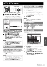
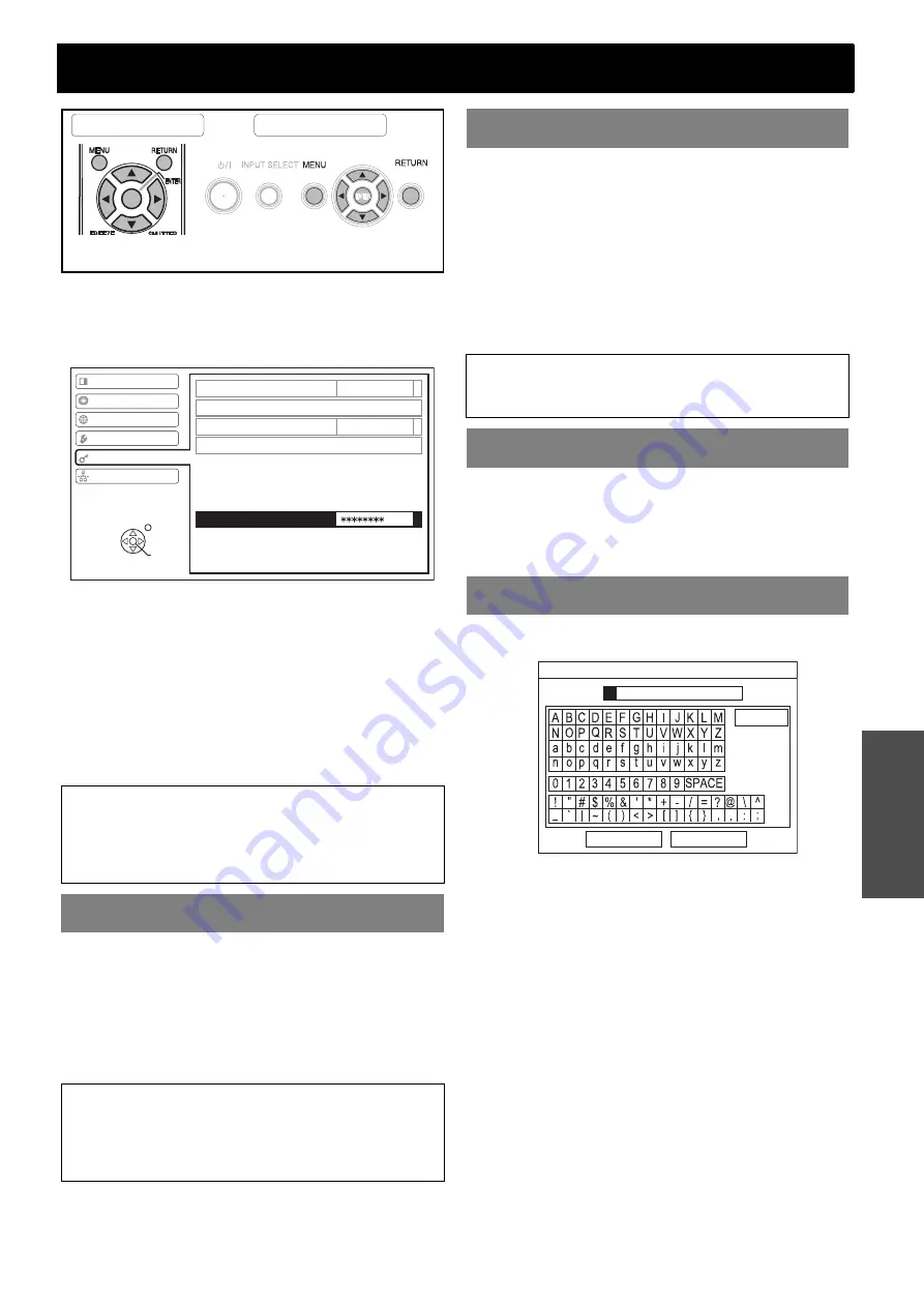
SECURITY menu

J

Entering the SECURITY menu

Every time when you apply to the 

SECURITY


menu, you will be asked to perform the password 
operation.

When you apply to the 

SECURITY

 menu before you 

change the password to your original, perform to input 
the following factory default password operation.


Press 

F


H


G


I


F


H


G


I

 and 

ENTER

.

Q

After you change the password

When you apply to the 

SECURITY

 menu after you 

change the password to your original in the 

PASSWORD CHANGE

 menu, input the original 

password operation.

You can activate the security system and the password 
operation will be asked to perform when the projecting 
mode started. Unless you perform the correct password 
operation, all of the button controls will be disabled 
except the 

POWER

 button.


OFF

Deactive


ON

Active

You can change the password operation to your original.

1. Press a series of button operation up to 8 as a 

password by using 

F


G


I

 and 

H

 buttons.

2. Press 

ENTER

.

3. Press the exact same series of button operation 

you entered in the 

NEW

 password box for 

confirmation.


If a series of button operation is incorrect, you will be 
asked to perform again.

4. Press 

ENTER

.

You can set your original text, such as company name or 
URL information, to display regularly at the bottom of the 
projected image while projecting.


OFF

Deactive


ON

Active

You can enter your original text up to 22 characters for 

TEXT DISPLAY

.

1. Use 

F


G


I


H

 to specify the location of the 

required character.

2. Press 

ENTER

.


The selected character will be displayed in the 

TEXT 

CHANGE

 box.

3. Repeat until finish your original text.


Select 

DELETE

 to delete the last entered character 

and press 

ENTER

.

4. Select 

OK

 and press 

ENTER

 to set the entered 

text.


Select 

CANCEL

 or press 

MENU

/

RETURN

 buttons to 

return to the previous menu.

NOTE:

• The factory default password is valid until you change 

the password in 

PASSWORD CHANGE

 menu.

• The entered password operations will appear as 

asterisks in the box.

INPUT PASSWORD

NOTE:

• When you activated the security system, make sure to 

change the password to your original for safety.

• The factory default password is valid until you change 

the password in 

PASSWORD CHANGE

 menu.

Remote control

Control panel


See “Navigating through the MENU” on page 29.


See “Main menu and Sub-menu” on page 30.

PICTURE

POSITION

INPUT PASSWORD

PASSWORD CHANGE

TEXT DISPLAY

TEXT CHANGE

PASSWORD

LANGUAGE

OPTION

SECURITY

NETWORK

OFF

OFF

SELECT

ENTER

RETURN

PASSWORD CHANGE

NOTE:

• The entered password operations will appear as 

asterisks in the box.

TEXT DISPLAY

TEXT CHANGE

OK

CANCEL

DELETE

TEXT CHANGE

Summary of Contents for PT-FW100NTE

Page 1: ...ENGLISH Operating Instructions LCD Projector Model No PT FW100NTE Before operating this product please read the instructions carefully and save this manual for future use TQBJ0217 3 Commercial Use...

Page 2: ...riod of time 2 To prevent electric shock do not remove cover No user serviceable parts inside Refer servicing to qualified service personnel 3 Do not remove the earthing pin on the mains plug This app...

Page 3: ...propriate waste handling For more information about collection and recycling of old products and batteries please contact your local municipality your waste disposal service or the point of sale where...

Page 4: ...bH Panasonic Testing Centre Winsbergring 15 22525 Hamburg F R Germany Ce produit est con u pour l utilisation dans les pays suivants Autriche Belgique Bulgarie R publique Tch quie Chypre Danemark Esto...

Page 5: ...Important Safety Notice ENGLISH 5 Important Infomation...

Page 6: ...ng the input signal 24 Positioning the image 24 Remote control operation 25 Operating range 25 Setting up the image position automatically 25 Switching the input signal 26 Using the laser pointer 26 C...

Page 7: ...TUP 37 SIGNAL SEARCH 37 INSTALLATION 37 SCREEN SIZE 37 HIGHLAND 38 TEST PATTERN 38 DETAILED SETUP 38 SECURITY menu 39 INPUT PASSWORD 39 PASSWORD CHANGE 39 TEXT DISPLAY 39 TEXT CHANGE 39 NETWORK menu 4...

Page 8: ...he mains socket If the plug is not inserted correctly electric shocks or overheating could result Do not use plugs which are damaged or mains sockets which are coming loose from the wall Do not place...

Page 9: ...o the projector Do not place the projector in narrow badly ventilated places such as closets or bookshelves Do not place the projector on cloth or papers as these materials could be drawn into the air...

Page 10: ...least once a year If dust is left to build up inside the projector without being cleaned out it can result in fire or problems with operation It is a good idea to clean the inside of the projector be...

Page 11: ...s a high pressure mercury lamp and that is characterised as follows The brightness of the lamp depends on the duration of use The lamp may explode or shorten the lamp life by shocks or chipping damage...

Page 12: ...you use the projector at high elevation the HIGHLAND setting need to be ON to set the fan speed high Press I H to select the required option If you need to return to the INSTALLATION press F OFF The...

Page 13: ...he settings to the factory default settings page 27 Turn off the projection temporarily page 27 Display the frozen image while the display of subsequent images continues page 27 See CD ROM contents Co...

Page 14: ...e Sensor page 32 Speaker Lens shift lever page 18 Projection lens Front panel cover Hold both side of the top corner of the Front panel cover to open or close While not operating the controls panel ke...

Page 15: ...gnals corresponding to COMPUTER1 IN and or COMPUTER2 IN 1 OUT Air exhaust port Heated air comes out of this opening VARIABLE AUDIO OUT Connect an audio cables for outputting audio signals to the conne...

Page 16: ...1 1 78 m 70 0 94 m 3 1 1 51 m 4 11 2 0 m 6 6 4 0 m 13 1 2 03 m 80 1 08 m 3 6 1 72 m 5 7 2 3 m 7 6 4 6 m 15 1 2 29 m 90 1 21 m 3 11 1 94 m 6 4 2 6 m 8 6 5 1 m 16 8 2 54 m 100 1 35 m 4 5 2 15 m 7 2 9 m...

Page 17: ...FRONT DESK INSTALLATION REAR DESK J Mounting in the ceiling and projecting from front J Mounting in the ceiling and projecting from rear INSTALLATION FRONT CEILING INSTALLATION REAR CEILING NOTE A tr...

Page 18: ...ace the projector where the projector lens is up to 24 horizontally off centre from the screen and then adjust the image position with the Lens shift lever Q Vertical shift You can place the projector...

Page 19: ...ill get the best quality of the projection image When the Lens shift lever is at the vertical limit of the shift range you cannot move the lever to the horizontal limit likewise when the Lens shift le...

Page 20: ...See List of compatible signals on page 46 J LAN terminal Before connection to the projector Connecting with computers NOTE When COMPUTER2 SELECT in the OPTION menu is set to OUTPUT do not connect any...

Page 21: ...with AV equipment NOTE When you connect more than one AV equipment switch the audio connection manually NOTE If you connect the BNC cables use with a commercial BNC RCA adaptor DVD player Audio syste...

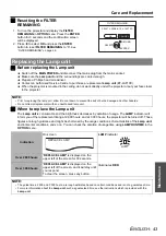
Page 22: ...tart the projection NOTE Do not use other than a provided Mains lead Ensure all the input devices are connected and turned off before connecting the Mains lead Do not force the connector as this may d...

Page 23: ...ANGE while cooling the lamp then illuminates RED when is ready to switch off the MAIN POWER 4 Switch off the MAIN POWER on the back of the projector Switching on the projector NOTE When starting up th...

Page 24: ...le vertically See Front leg adjusters and throwing angle on page 17 4 Adjust the focus and the projected image size Turn the Focus lever and Zoom lever to adjust the image You can confirm the adjusted...

Page 25: ...tion may not be effective with a translucent screen You can adjust the setting of POSITION DOT CLOCK and CLOCK PHASE in the POSITION menu automatically for the projected COMPUTER signal image Operatin...

Page 26: ...r an accidental operation 1 Open the battery compartment cover of the Remote control 2 Slide the switch tab 3 Close the battery compartment cover of the Remote control See Battery compartment on page...

Page 27: ...tinues on the right To escape from the INDEX WINDOW press the MENU or RETURN button Q Switching the position In default the frozen image is displayed on the left and the subsequent image is displayed...

Page 28: ...ress F G I H to shift the centre point You can control the volume of the built in speakers and output sound Press to control the volume Projecting 2 images at a time NOTE FREEZE and VOLUME controls ar...

Page 29: ...tems disappear from the screen Called up item will be disappear after 5 seconds and return to the menu mode If there is a lower level the next level will be displayed 3 Press I H to adjust or set the...

Page 30: ...ignals Default 0 page 32 TINT 2 Default 0 page 32 SHARPNESS Default 0 page 32 COLOR TEMPERATURE LOW STANDARD page 32 HIGH DAYLIGHT VIEW AUTO ON page 32 OFF DETAILED SETUP 3 3 VIDEO S VIDEO COMPUTER si...

Page 31: ...TUP AUTO BUTTON page 37 SIGNAL SEARCH ON OFF page 37 INSTALLATION FRONT DESK REAR DESK page 37 FRONT CEILING REAR CEILING SCREEN FORMAT 16 9 16 10 page 37 HIGHLAND OFF ON page 38 TEST PATTERN page 38...

Page 32: ...n in well lit rooms where the ambient light sources cannot be controlled such as when a door opens or when window coverings fail to block out sunlight AUTO Automatic adjustment ON Active OFF Deactive...

Page 33: ...ctive Q NOISE REDUCTION You can switch the automatic noise reduction system on off Press I H to select the required setting ON Automatic noise reduction OFF No noise reduction J For RGB signals Q WHIT...

Page 34: ...e in proper ratio Q 4 3 When a 4 3 or 5 4 signal is detected the image will be projected without any change and other signals will be adjusted to 4 3 with preserving original ratio Q 16 9 When a 16 10...

Page 35: ...e portions may be cropped Select an aspect ratio which preserves the intention of the image creator The order of ASPECT types is defined not only by the input method but also by the input signals See...

Page 36: ...the required option You can check the remaining amount of the ARF Auto Rolling Filter The colour of the bar scale is indicating the condition of the ARF Yellow The filter remaining amount is getting l...

Page 37: ...ion will be adjusted for DOT CLOCK and CLOCK PHASE See Remote control on page 13 You can turn off the auto signal detecting system ON Detect the input signal from the terminals and project the image O...

Page 38: ...s J BACK COLOR You can choose a BLUE or BLACK screen for when the projector is idle Press I H to select the required option J VOLUME You can adjust the volume of the built in monaural speaker and VARI...

Page 39: ...al text such as company name or URL information to display regularly at the bottom of the projected image while projecting OFF Deactive ON Active You can enter your original text up to 22 characters f...

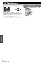
Page 40: ...PASSWORD PASSWORD CHANGE NETWORK STANDBY WEB CONTROL LIVE MODE CUT IN STATUS INITIALIZE NOTE See more detailed instructions in the contents of the CD ROM which is provided with the projector Remote c...

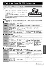
Page 41: ...the Lamp unit on page 43 Let the Lamp unit cool down and turn on the MAIN POWER Contact an Authorised Service Centre See Replacing the Lamp unit on page 43 Indicator Illuminating RED and still project...

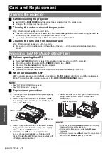
Page 42: ...100 J When to replace the ARF ARF is consumable product and effects on ventilation FILTER indicator will inform you of the replacement timing You can check the remaining amount of the ARF in FILTER RE...

Page 43: ...ement timing at 2 800 hours and at 3 000 hours the projector will be turned off Those figures are rough guidance and might be shortened by the usage conditions characteristics of the Lamp unit environ...

Page 44: ...ety cable provided with the projector is installed and attached to the bottom of the projector when mounting in the ceiling for safety and security J Installing the safety cable 1 Install the ceiling...

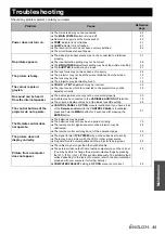
Page 45: ...properly A cable may be connected to the VARIABLE AUDIO OUT terminal The volume adjustment may be at the lowest possible setting 20 15 28 The control buttons of the projector do not operate CONTROL PA...

Page 46: ...37 5 50 0 74 3 A VESA 640 x 400 31 5 70 1 25 2 A COMPUTER 640 x 400 37 9 85 1 31 5 A VGA480 640 x 480 31 5 59 9 25 2 A 640 x 480 35 0 66 7 30 2 A 640 x 480 37 9 72 8 31 5 A 640 x 480 37 5 75 0 31 5 A...

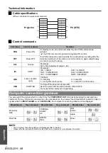
Page 47: ...xt command When a command which does not require parameters to be sent the colon is not required If an incorrect command is sent from the personal computer the ER401 command will be sent from the proj...

Page 48: ...ter the lamp has switched off the lamp is not turned back on again straight away in order to protect the lamp AVL Volume Parameter 000 063 Adjustment value 0 63 IIS INPUT Parameter VID VIDEO RG1 COMPU...

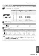
Page 49: ...ol by external contact Pin No Settings B A Short Open Operation On Off Pin No Settings C A Open Open Short Short Short Open E A Open Short Open Open Short Short F A Open Open Short Open Open Short Inp...

Page 50: ...nvironment Temperature 0 C 40 C 32 F 104 F When the HIGHLAND page 38 is set to ON 0 C 35 C 32 F 95 F Humidity 20 80 no condensation Scanning frequency 2 for RGB signal 2 See List of compatible signals...

Page 51: ...ine 0 5V rms M3 jack Stereo MINI Monitor output stereo compatible 0 V rms 2 0 V rms variable SERIAL D sub 9 pin RS 232C compatible REMOTE D sub 9 pin For external control LAN RJ 45 Single line For net...

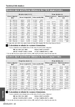
Page 52: ...5 m 11 5 70 1 78 m 0 87 m 2 10 1 55 m 5 1 2 0 m 6 6 4 1 m 13 5 80 2 03 m 1 00 m 3 3 1 77 m 5 9 2 3 m 7 6 4 7 m 15 5 90 2 29 m 1 12 m 3 8 1 99 m 6 6 2 6 m 8 6 5 3 m 17 4 100 2 54 m 1 25 m 4 1 2 21 m 7...

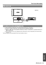
Page 53: ...o and High Definition Multimedia Interface are trademarks or registered trademarks of HDMI Licensing LLC The font used in the on screen displays is a Ricoh bitmap font which is manufactured and sold b...

Page 54: ...W 32 DEFAULT Remote control 27 Remote control button 13 DETAILED SETUP OPTION menu 38 PICTURE menu 33 DIGITAL ZOOM Remote control 28 Remote control button 13 Dimensions 53 Direct power off 22 DIRECT P...

Page 55: ...rol panel button 14 Remote control button 13 S Safety cable Accessories 11 Safeguards 44 SCREEN SIZE 37 Screen size 16 10 16 16 9 52 4 3 52 Security lock 15 SECURITY menu 39 SERIAL 15 Basic format 47...

Page 56: ...Printed in Japan S0507 5108F...

Reviews: